
- Do not use blower or infotainment system in idle condition.
- Ensure door, hood and tail gate are properly locked.
- Shift to P before switching off ignition.
- Please do not use Accelerator & Brake pedal simultaneously
- Prohibited to drive the vehicle in flood / high water level conditions


- Vehicle Identification Number (VIN)
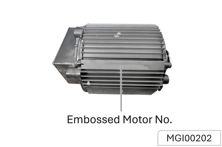
- Drive Motor Production Number
Always quote the Vehicle Identification Number (VIN) when communicating with JSW MG Authorized Service Center. If the drive motor or electric drive system is involved, it may be required to provide the identification numbers of these assemblies.
Vehicle Identification Location
Vehicle Identification Number (VIN)
- The vehicle identification plate is located on the door frame of codriver side door.
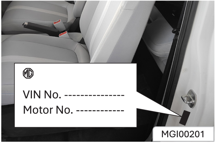
The VIN information can be extracted from the vehicle using the approved diagnostic equipment present at JSW MG Authorized Service Center.
Drive Motor Production Number Mark No.
Stamped on the lower part of the drive motor housing.
a. Low voltage component: The LV equipment operates at 12V and includes things like instruments, audio systems, lights, horns, and blowers.
Switch off LV equipment when not in use to avoid 12V battery drain.
b. High voltage component:
HV equipment includes the drive motor, motor controller, HV battery pack, charging system, A/C compressor, and heater.
Each HV component has a warning label. Please pay attention to relevant warnings. To avoid electric shock, do not touch any EV components, HV cables & other connectors. Do not touch any exposed or damaged orange HV cables, otherwise you may be exposed to a risk of electric shock. Please read and follow these warnings carefully to avoid electric shock. Do not touch any HV components or cables.
After you receive the vehicle, make sure to fully charge the HV battery to 100% before it drops below 30% to keep it in good condition.
a. HV component safety:Avoid touching exposed or damaged orange HV cables.
b. High-voltage system:Water contact
The high-voltage system remains generally safe in the following scenarios:
- Vehicle partially submerged in water up to 300 mm.
- Leakage of liquids in the trunk.
In these situations, there is no risk of electric shock. However, there is a possibility of other damage to the vehicle.
c. Avoid modifications:
Do not take disassemble or modify any electrical parts in the vehicle. Modifying them could lead to serious problems like short circuits, fires, or burns. Improper execution of the work poses a risk of fire and serious injury from electric shock caused
by the high-voltage system. JSW MG MOTOR advises that modifications and maintenance on the vehicle should only be conducted by JSW MG authorised service center. The high-voltage system in your vehicle is selfcontained, ensuring safety as long as no unauthorized work is done on high-voltage electrical parts or the chassis.
a. Accident response:
If there’s an accident and you have time, turn off the vehicle’s power, set the parking brake, turn on hazard lights, place a warning triangle, and leave the vehicle. Contact the JSW MG authorised service centre right away. If there’s no time, like if there’s a fire or strong burning smell, turn off the vehicle and activate the parking brake to get out. . Accident response:
b. Fire or smoke situation:
Immediately turn off the power supply and get off the vehicle. If the fire is intensive or develops rapidly, stay away from the vehicle immediately and call 101. If the fire is not intensive, use a waterbased fire extinguisher to put out the fire and keep a safe distance from the fire source.
a. Battery replacement and recycling:
If you need to replace the HV battery, handle it carefully to avoid injury. According to Indian laws & regulations, recycle the HV battery at an MG-designated recycling station. Disposing of these batteries improperly can harm the environment and people. Check the official website for recycling details
b. Battery maintenance:
When the instrument cluster’s power bar turns red, it means the HV battery is low. Charge it promptly and avoid letting it completely run out before charging again. This helps keep the battery working well. It is recommended to fully charge the battery at least once every two weeks when using the vehicle regularly for maintenance.
Do not alter the charging port or equipment. Doing so could lead to charging problems or even cause a fire or may lead to fatal injuries.
Do not dismantle or open the lithium-ion HV battery pack without authorization. In case of accidents, professionals should not cut or impact the battery pack to avoid leaks, deformation, and potential injury.
Before storing the vehicle for an extended period (over one month), ensure the battery is charged to more than 50%. After prolonged parking, perform charging maintenance at least once a month. This involves fully charging the vehicle using AC slow charging, then discharging it to between 40% and 60% before parking again. Failure to maintain the battery as recommended could lead to vehicle issues caused by over-discharge, which may not be covered under warranty.
Be extra cautious of pedestrians. Since the vehicle is quiet and doesn't make noise from the engine, pedestrians might not realize it's approaching, moving, or getting ready to move, and could accidentally step into its path.
- EV - Electric Vehicle
- HV battery - High Voltage battery
- LV battery - Low Voltage (12V) battery
- AC - Alternating Current
- DC - Direct Current
- OBC - On Board Charger
- PDU - Power Distribution Unit
- VCU - Vehicle Control Unit
- BMS - Battery Management System
- OBD - On Board Diagnostics
- SoC - State of Charge
- SRS - Supplementary Restraint System
- CRS - Child Restraint System
- DAB - Driver Airbag
- PAB - Passenger Airbag
- ABS - Anti-lock Braking System
- EBD - Electronic Brake Force Distribution
- ESC - Electronic Stability Control
- PEPS - Passive Entry/Passive Start
- ESCL - Electronic Steering Column Lock
- EPAS - Electric Power Assisted Steering
- LED - Light Emitting Diode
- DRL - Daytime Running Lamp
- ORVM - Outside Rear View Mirror
- IRVM - Inside Rear View Mirror
- AUTO-IRVM - Auto Inside Rear View Mirror
- HVAC - Heating Ventilation and Air Conditioning
- FATC - Fully Automatic Temperature Control
- DIS - Driver Information System
- DTE - Distance to Empty
- IGN - Ignition
- ACC - Accessory
- EPB - Electronic Parking Brake (EPB)
- CPL - Centre Positioning Light
This section of the manual, along with others, contains crucial safety guidelines. Please pay special attention to the following precautions:
a. Always use your seat belt
It provides the best protection in any type of accident. Airbags are designed to complement seat belts, not to replace them. Therefore, even though your vehicle has airbags, ALWAYS ensure that you and your passengers wear your seat belts and wear them correctly.
b. Secure all children
All children under the age of 13 should ride in the back seat of your vehicle, properly restrained. Infants and small children should be secured in an appropriate Child Restraint System. Older children should use a booster seat with a lap/shoulder belt until they can safely use the seat belt alone, without the booster seat.
Adjusting the seats so that you are sitting in a safe and comfortable position plays an important role for the safety of the driver and passengers, as much as seat belts and air bags when in an accident.
Do not use a cushion that reduces friction between the seat and the passenger. The passenger's hips may slide under the lap portion of the seat belt during an accident or a sudden stop. Serious or fatal internal injuries could result because the seat belt cannot operate properly.
c. Safety precautions
Adjusting the seats so that you are sitting in a safe and comfortable position plays an important role for the safety of the driver and passengers, as much as seat belts and air bags when in an accident.
d. Airbag risks
Though airbags can be life-saving, they can also cause serious or fatal injuries to those who are too close or not properly restrained. Infants, young children, and shorter adults are especially at risk. Adhere to all instructions and warnings provided in this manual regarding airbags.
e. Avoid driver distraction
Driver distraction is a significant and potentially fatal hazard, particularly for inexperienced drivers. Always prioritize safety and be aware of distractions like drowsiness, reaching for objects, eating, grooming, interacting with other passengers, and using mobile phones. To minimize distraction:
Set up mobile devices (e.g., phones, navigation units) only when your vehicle is parked or stopped.
Use mobile devices only when permitted by laws and when it is safe. Never text or email while driving; many places have laws against texting and some also ban handheld phone use.
Do not let mobile device use distract you from driving. It’s you responsibility to ensure that both hands remain on the wheel and your attention stays on the road.
f. Maintain appropriate speed: Driving at excessive speeds is a leading cause of accidents and injuries. Higher speeds increase the risk of severe consequences, although serious injuries can also occur at lower speeds. Always drive at a safe speed for the current conditions, regardless of posted speed limits.
g. Ensure vehicle safety: Tyre blowouts or mechanical failures can be dangerous. To minimize these risks, regularly check your tire pressures and conditions, and follow all scheduled maintenance guidelines.
Seat Position and Backrest Normal Condition
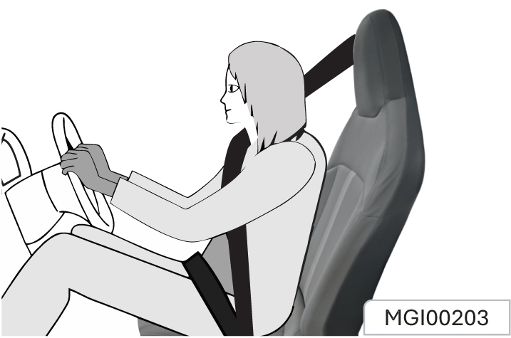
- When you sit on the seat, make your hip as close to the backrest as possible. Adjust the distance between the seat and the pedal so that your leg slightly bends when you depress the pedal. The passenger’s seat shall slide as backward as possible.
- When you sit on the seat, make your shoulders lean on the backrest as backward as possible. Set the backrest inclination angle to make your arm conveniently to reach the steering wheel while slightly bending the arm. Keep the shoulders leaning against the backrest while turning the steering wheel. The backrest shall not incline excessively backward. We suggest that the inclination angle of all backrests shall not be more than 25°.
- The seat height shall be so set that the occupant can see all directions and the positions of all display instruments. The head must be at least one hand away from the roof lining. The thighs are right on the seat without constriction.
Seat Adjustment
Seat Position Adjustment
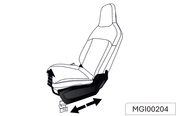
Seat Backrest Adjustment
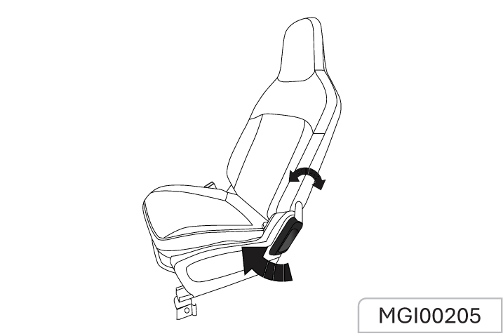
Front Passenger Seat One-button Access*
Unlock the handle according to the direction shown in the figure, and adjust the backrest to the foremost end.
When it is confirmed that the backrest is in the foremost position, the slide rail is triggered to unlock, and the seat can slide freely forward and backward to facilitate the entry and exit of rear passengers.
Adjust the backrest backward to an appropriate position, and the seat slide rail will return to the locked state.
The seat belt is designed only for one passenger to use. They are not applicable to a passenger under 12 years old or under 150 cm high. Check all parts of the seat belt system for any damage or abnormal function regularly
Please replace the damaged parts and components. It is strongly recommended to have the seat belt or used seat belt tensioner replaced at the Aftersales Service Center after an accident
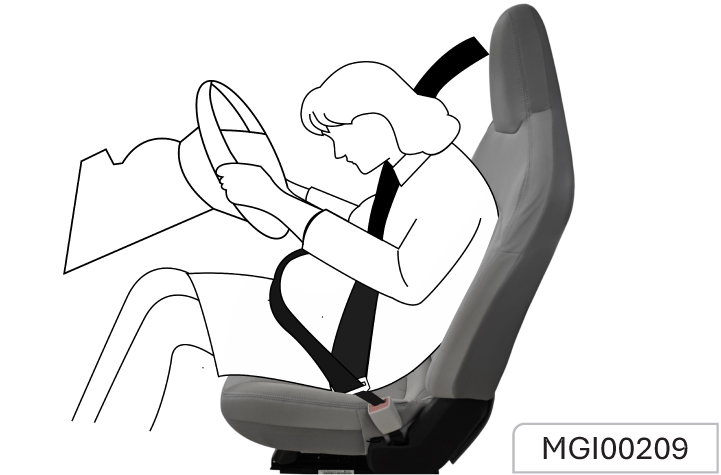
Wearing
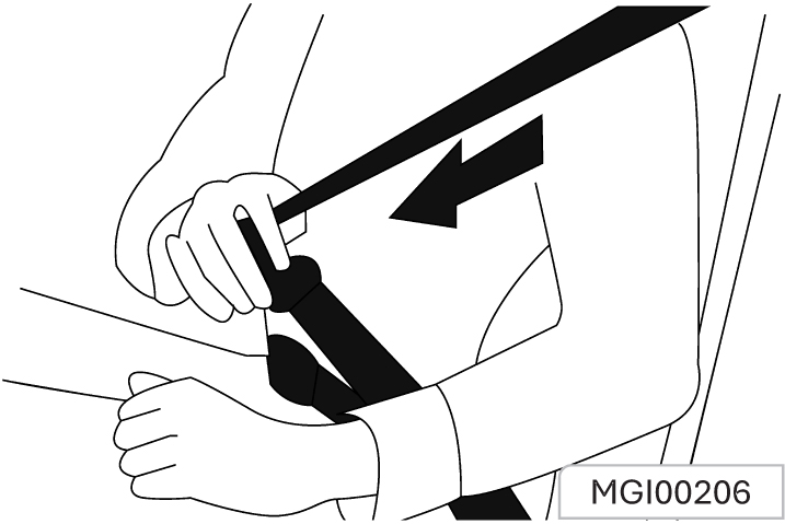
1. Pull out the seat belt from the retractor, and fasten it across the body without twisting.
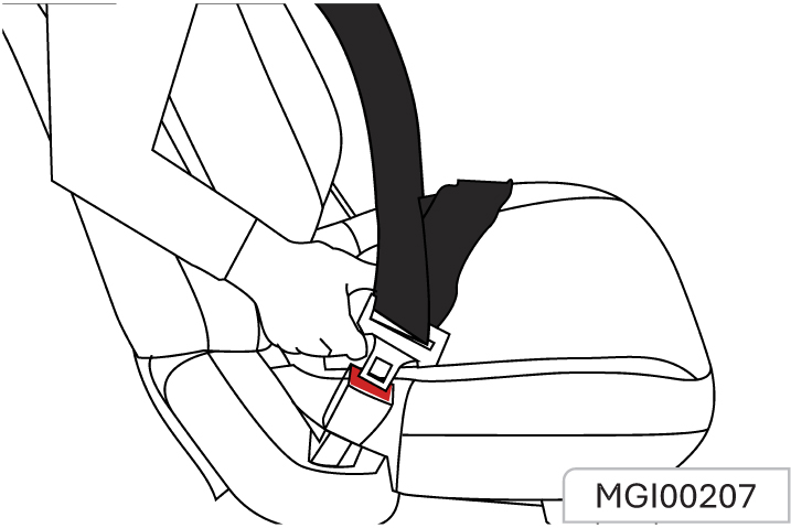
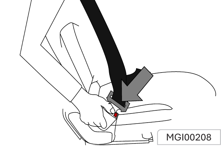
2. Put the latch plate in the buckle for fixing.
When driving, pull the shoulder belt forcibly to adjust the tightness of hip belt.
Too loose or heavy clothing will hamper close wearing the seat belt. Do not place any object (such as handbag and mobile phone) between the seat belt and your body.
Unlock
To unbuckle the seat belt, please press the red button on the buckle.
Seat Belt Use During Pregnancy
The seat belt provide protection for everybody, including a pregnant woman. Like all passengers, if pregnant women do not wear the seat belt, severe personal injuries are more likely to be caused to them. Pregnant women shall wear a hip/ shoulder seat belt during the whole pregnancy, and the hip belt shall be fastened as low as possible. The best way to protect a fetus is to provide safety protection to its mother. If the seat belt is fastened correctly, the fetus is not vulnerable to injury in case of a collision. Wearing the seat belt correctly is the key to providing the best protection for pregnant women and anyone else.
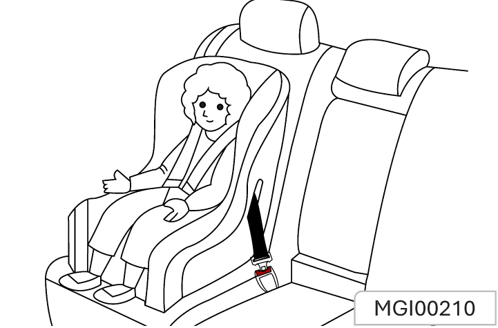
Child Seat
The vehicle is not equipped with a child seat.
If you want to add one, a child seat that is applicable to ISOFIX “general” type can be selected. A child seat can only be placed on the second row because the front seat is not equipped with the anchor system bracket.
The statistical data of accidents show that placing the child seat on the second row seat can largely improve the child safety.
According to European Regulation ECE R44, child restraint systems can be divided into the following 5 groups:
Group 0: For children weighing less than 10 kg.
Group 0+: : For children weighing less than 13 kg.
Group I:: for a child weighed between 9 kg to 18 kg.
Group II: : for a child weighed between 15 kg to 25 kg.
Group III: for a child weighed between 22 kg to 36 kg.
Please select a suitable child seat according to your child’s weight and body size.
For children under 1 year old, a rear-facing child seat must be used as their bones are still fragile.
Approved Child Restraint Position (for non ISOFIX Child Restraints)
| Mass Group | Seating position (or other side) | |||||||||
|---|---|---|---|---|---|---|---|---|---|---|
| Front passenger | Second OB | Second Centre | Third OB | Third Centre | ||||||
| LH | RH | LH | RH | |||||||
| Group 0 up to 10kg | X | X | X | NA | NA | NA | NA | NA | ||
| Group 0 up to 13kg | X | X | X | X | NA | NA | NA | NA | ||
| Group I 9 to 18kg | X | X | X | X | NA | NA | NA | NA | ||
| Group II 25 to 25kg | X | X | X | X | NA | NA | NA | NA | ||
| Group III 22 to 36kg | X | X | X | X | NA | NA | NA | NA | ||
|
Note: Description of letters in the table: U - Suitable for universal child restraint systems approved for this mass group. X - Seat position not suitable for child restraint systems in this mass group. |
||||||||||
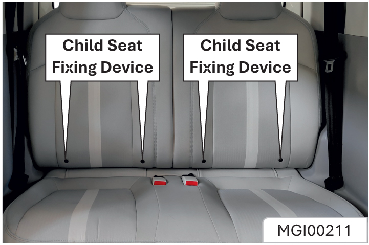
Child Seat Fixing Device
Adjust the child seat
- The child seat fixing device is on the joint between the second row set backrest and the seat cushion. Its position can be identified by a label at the lower end of the seat back. The left and right seats are equipped with a child seat fixing device respectively.
- Clear up the objects on the seat. Remove the seat belt and seat belt buckle to avoid affecting the accurate fixing of the child seat.
- Put the child seat on the second row seat.
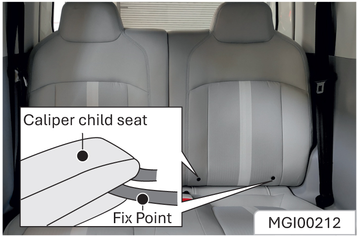
- Connect the fixing hook on the child seat to the on vehicle fixing device. Operate according to the child seat instructions.
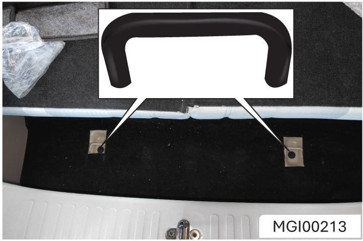
- Connect the upper strap of the child seat to the rear fixing point of the vehicle. These fixing points are present under the carpet behind the second row Refer to the child seat instructions to get to know when and how to strain the upper strap.
- Push and pull the child seat in all directions to make sure it is safely secured.
- Make sure that the child seat temperature is not very high before putting a child in the seat. In case of a serious collision accident, the child seat fixing device may be damaged. Some parts may require repair and replacement. Please check the child seat fixing device after a collision.
The vehicle may have the following airbags:
- Driver frontal airbag
- Co-driver airbag
For all airbags, the letter “AIRBAG” is marked on the trim panel or the label near the opening where they are deployed. The word “AIRBAG” on the driver’s airbag is located in the middle of the steering wheel, the front passenger’s frontal airbag word is located on the instrument panel.
The airbag can supplement protection on the basis of correct wearing of the seat belt
Although nowadays the airbags are designed to reduce the injury risks caused by the impact force when the airbag is inflated, all airbags must be inflated rapidly to exert its effect.

On the instrument panel, there is an airbag indicator which displays the airbag shape symbol. The system will check whether the airbag circuit system has a fault and give .corresponding prompt through the indicator.
Refer to the Chapter “Instruments and Controls” for detailed information.
Driver Frontal Airbag
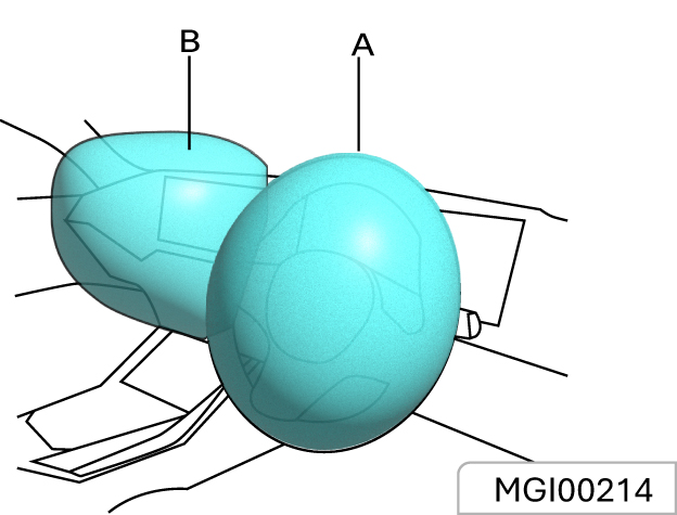
As shown in the Figure A above, the driver frontal airbag is located in the middle of the steering wheel.
As shown in Figure B, the front passenger frontal airbag is located on the front passenger side instrument panel.
Other situations where the airbag may inflate except for collisions.
If the vehicle bottom is impacted seriously, the airbag may also be inflated. Refer to the following examples.
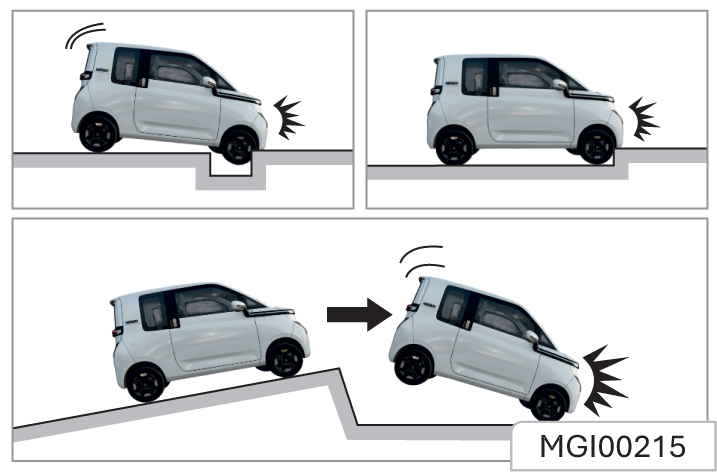
- Hit a road shoulder, sidewalk edge or hard surface.
- Fall into or drive into a deep pit.
- Wheel hard landing or vehicle fall.
Frontal airbag may not be inflated in the following collisions.
The frontal airbag will usually not be inflated in case of side collisions, rear-end collision by another vehicle, turnover or low-speed headon collisions. Regardless of the collision type, the driver’s frontal airbag will only inflate if the vehicle generates sufficient forward deceleration.
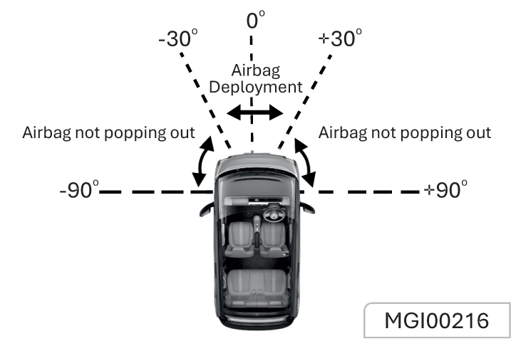
- Head-on collision angle over 30° from vehicle longitudinal direction.
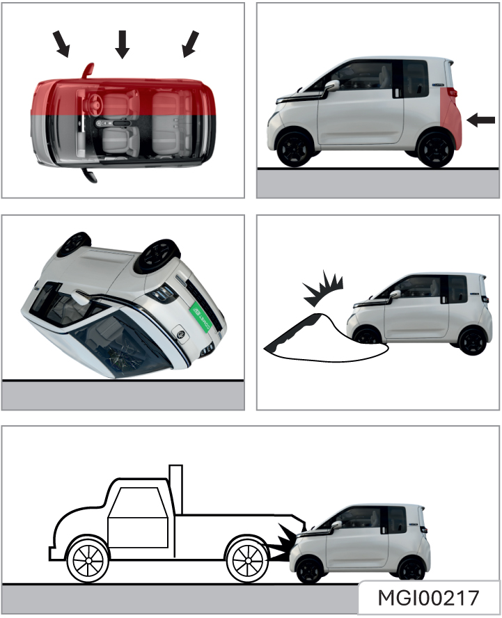
- Side collision
- Rear-end collision
- Overturn, falling from high place, rolling.
- Hit deformable objects, such as sandpile, guard bar, column and tree.
- Hit into front vehicle bottom, especially truck bottom.
Important Suggestion!
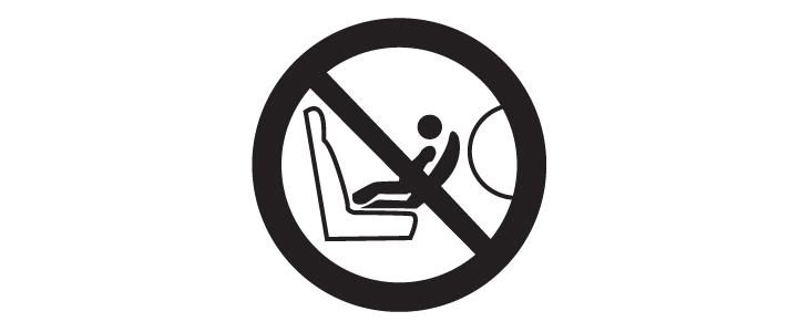
Do not install rear-facing child seats on front seats protected by airbags! Otherwise, children may be injured or even killed.
Important Note
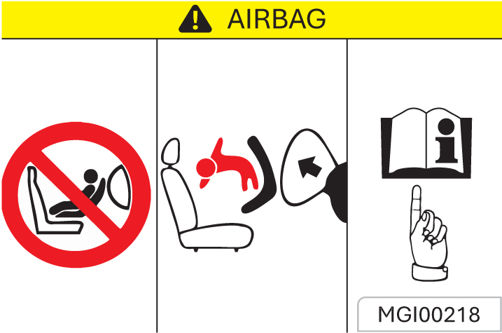
Do not use a backward-facing child restraint system on a seat (front seat) protected by a frontal air bag (in activated state). Otherwise, severe injuries or even death may be caused to the child when the air bag is deployed.
When shall the airbag be inflated?
The frontal airbag is designed to be inflated in moderate to severe headon collision or almost head-on collision to reduce severe injury risks of the driver’s and the front passenger’s head and chest.
Frontal airbag inflation is not primarily dependent on the speed of the vehicle, but on the object being collided with, the direction of the collision and the deceleration of the vehicle per unit time during the collision. The frontal airbag may be inflated at different collision speed.
It depends on whether the vehicle hits the object straight or at an angle at the moment of the collision, and on whether the collided object is fixed or moving, non- deformable or deformable, narrow or wide. Due to different designs of each model, the collision inflation conditions of the frontal airbag may vary. Frontal airbags do not inflate in the event of a vehicle rollover, a rear collision and many side collisions.
The frontal airbag may not inflate in slight headon or nearly head-on collisions, lateral or diagonal collisions, collisions to cylindrical objects (such as telegraph pole and tree trunk), rear-end collisions under large vehicle (trucks, etc.) breast board and lateral glancing collisions.
As per the design, the seat lateral impact airbag and the side curtain airbag will inflate according to the impact position in case of the moderate to severe lateral collisions.
The seat lateral-impact airbag and the side curtain airbag may not inflate in slight side collisions and lateral-frontal or diagonal collisions.
As per the design, the seat lateral impact airbag and the side curtain airbag will inflate on the collision side of the vehicle. Airbags are not triggered in every collision. For a particular accident, it shall not simply judge whether the airbag should be inflated according to the causalities, vehicle damage or repair and maintenance expenses. Your vehicle is equipped with a collision sensing and diagnosis module. If a collision accident reaches certain strength, the module may record relevant collision information after the collision. If you have any questions about the airbag working condition of your vehicle in a collision accident, please contact the JSW MG authorised service center in time for professional analysis and diagnosis
How is the airbag inflated?
During inflation, the sensing system sends an electronic signal that triggers the gas generator to release gas to fill the airbag, causing the airbag to inflate and eject from the cover. The gas generator, airbag and relevant members are all components of the airbag module. Please refer to “Airbag Position” for details
How does the airbag provide protection? The airbags supplement the protection provided by the seat belts by distributing the impact forces more evenly over the occupant’s body. However, in collisions where the occupant’s body is not moving in the direction of the airbag, and in collisions where an external object has entered the vehicle, the airbag is unable to provide the appropriate protection. The airbag shall only be seen as a supplementary device to the seatbelt.
When the airbag is inflated, dust may be spread in the air. All persons in the vehicle shall get off the vehicle as soon as possible. If you have a breathing problem and cannot get off the vehicle after airbag inflation, open the windows or doors to get fresh air. If breathing problems occur after the airbag is inflated, you should seek medical attention as soon as possible.
What will you see after the airbag inflates? When the airbag is inflated, it will deflate so quickly that some people may not even notice that the airbag has been inflated because it deflates so fast. Smoke and dust may also be emitted from the deflated airbag vent. If the vehicle power supply system can still work normally after a collision, the vehicle has the functions of automatically unlocking doors, turning on hazard warning lamps and turning off fuel system after airbag inflation. The driver can use corresponding function switch to lock doors, turn off indoors lamps and turn off the hazard warning lamp. The deployment of the front passenger air bag may also cause damage.
- An airbag is designed to inflate only once. After the airbag is inflated, some parts of the airbag system need to be replaced. Otherwise, the airbag system will be unable to provide protection in the next collision accident. The airbag system parts that shall be replaced include the airbag module, airbag control module, seat belt pretensioner and other parts.
- Work related to the SRS can only be done by JSW MG authorised Service Center technicians with corresponding qualification. Improper repair and maintenance may cause that the airbag system cannot function normally. Please drive to the JSW MG authorised Service Center for repair and maintenance.
Repair, maintenance and replacement of airbag system:
- The airbag system must be maintained by JSW MG authorised Service Center technicians. Improper maintenance will cause the airbag system to fail to function normally. Please go to the JSW MG authorised Service Center for repair and maintenance of the airbag system.
If the airbag cover is damaged, opened or broken, the airbag may not function normally. It shall be repaired as soon as possible.
Never stick or cover any object on the airbag cover surface or refit the airbag cover; never try to repair, adjust or remove or install any airbag system component; never try to refit the front bumper of the vehicle body by yourself.
Other situations where the airbag may be inflated (deployed) except for a collision the airbags may also inflate if the underside of the vehicle suffers a severe impact.
Refer to the following examples.
As one advanced electric braking system, the anti-lock brake system (ABS) is helpful in avoiding the vehicle from slipping and losing control, and this system can also provide the maximum braking capability on the slipped pavement.
When the ignition switch is turned on, the ABS warning lamp illuminates momentarily
The ABS warning lamp does not go out or illuminates when the vehicle is running, it indicates that the ABS is faulty. Please immediately contact the JSW MG Authorized Service center. Refer to “ABS Fault Warning Lamp” under Chapter “Instruments and Controls”.
The ABS will monitor the speed of each wheel during braking. If one wheel tends to be locked, the system will control brakes of two front wheels and two rear wheels respectively. When the ABS works, the brake pedal often vibrates slightly with noise.
The EBD system uses the high-speed computer to respectively induce and calculate different ground to which four Tyres are attached, and thus calculate different friction values at the moment the vehicle brakes. Therefore, the four Tyres can brake in different ways using different forces based on the conditions, and the ways and forces can be adjusted quickly during movement, so as to ensure that the vehicle is stable and safe.
The ESC system is a new type of active safety system, which represents the further development of anti-lock brake system (ABS) and traction control system (TCS) functions.
In addition, the system also adds a yaw rate sensor, a lateral acceleration sensor, and a steering wheel angle sensor. The front and rear driving force, braking force, and left and right wheels are controlled by ECU to ensure the lateral stability of the vehicle. The ESC system will automatically intervene when the driver drives at excessive speed or turns at high speed to ensure that the vehicle is under control again and safe. Indicators related to the ESC system include the ABS fault warning lamp, the EBD fault warning lamp, the ESC fault warning lamp, and the ESC off indicator.
- After the ignition switch is turned on, the indicator lights up for self-inspection. If the four indicators are on for 3s, it indicates that the ESC system is conducting self inspection and the indicators work normally. Under normal circumstances, all four indicators go out after 3 seconds
When the ESC system fails (such as improper installation, loose connector, and abnormal CAN communication), only the ESC off indicator will go out and the other 3 indicators will be on after 3s.
- If the ESC function is activated during driving, the ESC indicator will flash to remind the owner that the ESC system is running. If the ESC system cannot work normally when the ABS and EBD systems work normally, the ESC MIL will be on, indicating that the ESC system fails. If the ESC system and ABS system fail while the EBD system works normally, the ESC MIL and ABS MIL will be on. If the ESC system, the ABS system, and the EBD system fail, the ESC, ABS, and EBD fault warning lamps will light up.
- The ESC off indicator is to indicate that the ESC function is turned off (the indicator is on when the ESC function is off, and off when the ESC function is on). If the owner presses the ESC off button, some ESC functions will be off and the ESC off indicator will light up.
- The ESC system will be activated automatically after every re-ignition
When the ESC switch is pressed, the ESC system starts to work, and the ESC function will not be disabled immediately but after the process is completed. If the owner presses the ESC switch again, the ESC function will be enabled again. If the ESC switch is pressed for more than 10 seconds, the ESC system will consider it as a misoperation (For example, the ESC switch is accidentally pressed by other objects) and will not turn off the ESC function.
Turn off the ESC System*
The ESC function can be turned off by accessing the vehicle settings menu on the host. When the ESC function is turned off, the ESC off indicator lights up. It is generally not recommended to shut down the ESC system. The ESC system can be turned off temporarily only when the vehicle just leaves muddy ground or climbs a slope in a slippery area.
When the vehicle is in D gear or R gear at the half-slope start, after releasing the handbrake and brake pedal, the hill hold control function will be activated when the vehicle slides slightly, which can keep the vehicle parked on the slope for about 3-5 seconds. During this period of time, the vehicle will not slide, and the driver will be given a starting time to assist in climbing.
During the 3-5 seconds when HHC is activated, in case of any one of the following conditions, HHC will automatically exit:
- No operation is carried out by the driver. In this case, the hill hold control function will automatically exit after 3-5 seconds.
- The driver shifts gears (to N or P, or D/R). In this case, the hill hold control function will automatically exit.
- The accelerator pedal is depressed to start the vehicle and automatically exit the HHC.
When HHC is disabled, it will be activated again by one of the following operations:
- When the driver depresses the brake pedal or pulls the handbrake to stop the vehicle, the hill hold control function will be activated again
- After the accelerator pedal is depressed to start, if the vehicle stops and slides slightly, HHC will be activated again.
Releasing the handbrake and brake pedal will cause the vehicle to slide slightly.
- In case of low battery (<)25% or low ambient temperature ( 10°C), hill hold control power decreases or there is no power output. In such a case, please drive cautiously
- If the motor temperature is too high (the instrument will prompt) after continuous or frequent use of the hill hold control function, please pay attention to cooling the vehicle
- The greater the slope, the longer the sliding distance. Overloading may lengthen this distance. Therefore, please do not overload your car.
- Do not rely too much on HHC as it cannot replace the functions of brake and handbrake. Please drive carefully.
The Company is not responsible for any consequences arising from reliance on this system.
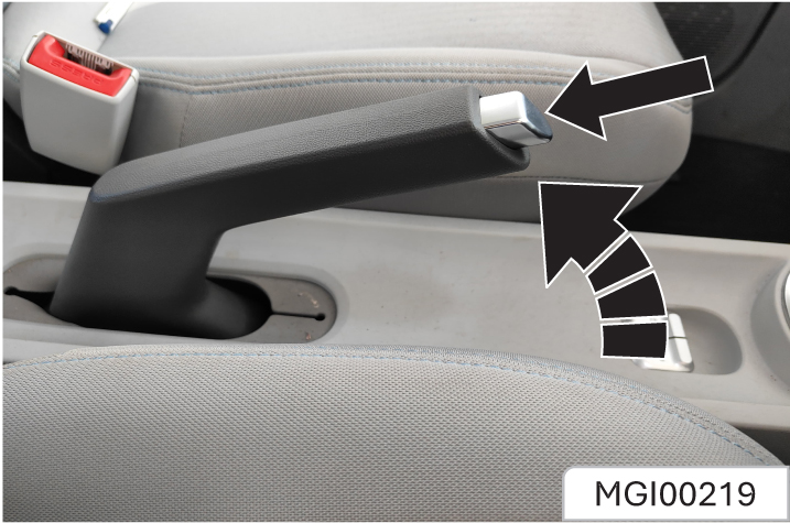
The parking brake impacts rear wheels.
The parking brake lever is between two front row seats. To operate the parking brake, stop the vehicle, press the brake pedal and pull the parking brake lever.
To release the parking brake:
- Press the brake pedal.
- Pull back on the parking brake lever slightly.
- Press the button on the parking brake lever joint.
- Release the parking brake lever when holding the button.
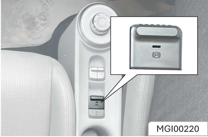
The parking brake impacts rear wheels. As shown in the figure above, the electronic parking brake (EPB) switch is between two front-row seats
Manually Activate the Parking Brake
To apply the parking brake, depress the brake pedal to stop the vehicle, and pull up the EPB switch. Release the EPB switch after the EPB working indicator lights up and P the instrument panel displays “Parking Brake Working”.
At this time, the EPB system clamps the vehicle to park.
Manually Release the Parking Brake
If the parking brake must be released, first make sure that the ignition switch is at the ON position, depress the brake pedal, and then press the EPB switch. The EPB working indicator goes out, and the instrument panel displays “Parking Brake Released” to remind you that the parking brake has been released.
If the brake pedal is not depressed, the instrument will command “please depress the brake pedal and then release the EPB switch”.
When the EPB switch is operated, the switch will respond only when it is released or pressed for more than 0.1s.
Deactivation of Automatic Clamping Function
When pushing, towing, and cleaning the vehicle, you may need to turn off the EPB automatic clamping function to drive the vehicle after startup.
Turn-off method: Depress the brake pedal and hold the EPB switch pressed while stopping the vehicle. Try to push the vehicle to confirm that EPB is not in the clamped state.
The vehicle with EPB has the auto vehicle hold function.
After the function is activated, the driver can depress the brake pedal to stop the vehicle, or depress the brake pedal to make the vehicle stand still and idle. After the brake pedal is released, the hydraulic pressure in the brake system will keep parking (whether on uphill or flat roads). At this time, the vehicle can be stationary without pulling up the EPB switch.
If the driver depresses the accelerator to start the vehicle within 5 minutes, the hydraulic pressure in the brake system will be automatically released, and the parking brake will be released at the same time to start the vehicle. After 5 minutes, automatically switch to the electronic parking brake caliper, clamp the parking, and release the hydraulic pressure in the brake system at the same time.
The start/stop state of the auto vehicle hold
function can be saved. If the auto vehicle hold switch is ON or OFF when the power supply is turned off last time, it will remain the same when the power supply is turned on again.
Automatic Vehicle Hold (AVH) Switch*
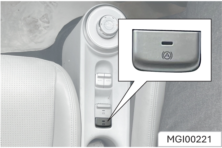
After the vehicle enters the READY state, the driver fastens the seat belt, closes the driver’s side door, and presses the auto vehicle hold switch. At this time, the background lamp on the switch illuminates, and the auto vehicle hold function is activated.
After that, if the conditions are met, the auto vehicle hold function working indicator on the instrument panel will light up. The parking brake starts to work, and the brake system applies braking force to park the vehicle.
Avoid sudden braking, starting and accelerating of the vehicle when the cup holder is in use to prevent liquid spillage. If hot liquid spills, it can result into burns. Such burn to the driver or co passenger could lead to loss of vehicle control & may result in accident.
- Do not place uncovered or unsecured cups, bottles, cans etc. in the cup holder containing hot liquid while the vehicle is in motion. Injuries may result in the event of sudden stop or collision.
- Keep cans or bottles out of direct sun light & do not put them in a hot vehicle. It may explode.
Keep your drinks sealed while driving to prevent liquid spillage. Liquid spills may get into vehicles electrical/electronic system & damage electrical/electronic parts.
When cleaning spilled liquids, do not dry the cup holder at high temperature. This may damage the cup holder.
The EPS system provides the steering assist for the vehicle.
The power steering fluid is not required for the system, which brings great convenience for the daily vehicle maintenance.
When the ignition switch is connected, the EPS fault warning lamp illuminates momentarily. The EPS fault warning lamp stays on or illuminates when the vehicle is running, it indicates the EPS system is faulty.
In this case, you need immediately go to Aftersales Service Center for maintenance.
When the EPS system is under extreme conditions of high load work for a long time (For example, the steering wheel is “turned to the end” for a long time, or the vehicle is moved into the garage at low speed repeatedly to a wide angle), the thermal protection function may be activated due to excessively high temperature of electrical elements.
The system will reduce the power assist after it enters the thermal protection state, and at the time you have to steer the wheel with great force. If the normal power assist need be recovered, you can steer the wheel at a smaller angle or promote the vehicle speed.
You can restart the vehicle when necessary.
HORN
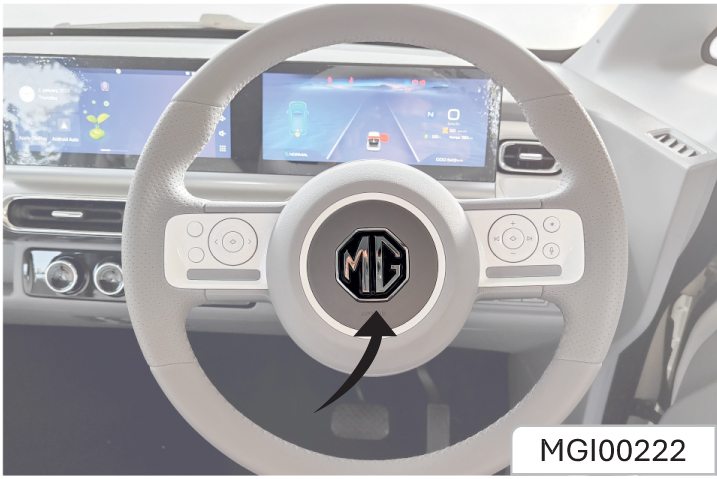
Press the center of the steering wheel to sound the horn.
After unlocking the vehicle, open the driver’s side door. The instrument cluster will activate, and the vehicle will enter the HV state. In HV state, all hybrid circuits are active, allowing you to engage the gear for driving and the A/C system can provide cooling while in HV state.
Trial run of new vehicle During the first 500 kilometers of driving a new vehicle, follow these steps to enhance performance, improve drive range efficiency, and prolong the vehicle’s lifespan:
- Avoid making sudden stops unless it’s an emergency. This helps the brakes settle in better.
- Try not to accelerate rapidly or drive at high speeds to prevent motor damage and conserve power.
- Do not tow another vehicle with your vehicle during this period.
a. Before you start your EV:
- Make sure that the area around the vehicle is clear.
- Do a check of the fluid levels - coolant, brake fluid, and windshield washer fluid as frequently as possible.
- Make sure that all windows and lights are clean.
- Examine the tires for their appearance, inflation pressure and condition.
- Make sure that all doors are closed.
- Position the seat and adjust the headrests.
- Adjust the inside and outside mirrors.
- Fasten seat belts and ask all passengers to do likewise.
- Do a check of the operation of the warning lights when the power switch is pushed to the ON position.
b. Procedure to start EV:
- With the smart key sit in the driver’s seat (if equipped), vehicle will automatically switch to HV mode.
- Fasten the seat belt before you start the vehicle.
- Turn off all electrical devices.
- Make sure to engage the parking brake for your safety.
- Make sure the accelerator and brake pedal have clearance with your right foot.
- Press the brake pedal to enter the READY mode, enabling the vehicle to operate in gear. The "READY" state is similar to the starting state of an internal combustion engine vehicle.
- The vehicle will get ON in ‘P’ mode only and it will be automatically selected.
- When ‘Ready’ message appears, you can drive the vehicle. Else, you cannot drive the vehicle. Start the vehicle again.
- Shift to the desired position (D/R).
- Release the parking brake and slowly release the brake pedal. See if the vehicle slowly moves forward, then press the accelerator pedal
If the EPB is disengaged manually after selecting required mode (D/R), release the brake pedal slowly to move the vehicle forward with creep activated condition. Further Accelerator pedal input to be given for achieving required speed.
c. Procedure to stop EV
- Hold down the brake pedal while the vehicle is parked.
- While pressing the brake pedal, shift to P mode using the gear knob to engage the parking brake.
The vehicle must always be put in ‘N’ when you stop the vehicle before engaging the park brake.
When the 'Ready' indicator is illuminated and the gear shifter is not in the Neutral (N) position, the driver may inadvertently press the accelerator pedal, resulting in unexpected vehicle movement.
d. Range of your EV: Your EV can provide specified range, when the high voltage battery is 100 percent charged. However, the range may vary in different driving modes and in certain situations like driving at high speed or when the air conditioner/heater/infotainment system is ON as the HV battery consumes more energy.
The vehicle battery usage is displayed in the instrument cluster in the form of estimated range.
Displayed range in the instrument cluster is a tentative number. It is recommended to keep 20 Km buffer in estimated range before planning the trip.
Tips to get maximum range while driving EV
1. If safe to do so, modulate the accelerator pedal instead of using the brake pedal when gradually slowing down. Whenever the vehicle is moving and you are not pressing the accelerator pedal, regenerative braking slows down the vehicle and feeds surplus energy back to the HV battery.
2. Limit the use of resources such as heating, and air conditioning. If you operate the air conditioner/heater for long duration, it will use too much electricity from HV battery.Turn OFF the heater and air conditioner if you do not need them.
3. Using the climate control system to heat the cabin when the outside temperature is below 0°C uses more electricity and affects vehicle range more than when using the heater when the temperature is above 0°C.
4. Press and hold the accelerator pedal to maintain speed and drive economically.
5. Gradually press and release the accelerator pedal when accelerating or decelerating.
6. Do not use unnecessary electrical components while driving.
7. Do not load unnecessary items in the vehicle trunk. Any additional load in the car drains the battery. Do not add more accessories, do not keep dead weight in the car, and in general travel as light as possible.
8. Do not mount parts on the exterior of the car as it might increase drag.
9. Service schedule should be adhered to. Fluid levels should be maintained within tolerance limits. Both of these also helps in realizing the maximum range potential of an electric vehicle
10. To optimize driving range use drive/eco mode and maintain the recommended tyre pressure.
11. Drive in ECO mode
12. ECO mode helps reduce power consumption by reducing acceleration when compared to the same accelerator pedal position in the D (Drive) position.
13. Drive at a constant speed. Maintain cruising speeds with constant accelerator positions as much as possible.
14. Accelerate slowly and smoothly. Gently press and release the accelerator pedal for acceleration and deceleration.
15. Vehicle range may be substantially reduced in extremely cold conditions (for example, 0°C).
16. Release the accelerator pedal to slow down and do not apply the brakes when traffic and road conditions allow.
- If conditions permit, it is recommended that you charge the vehicle when parking it. Shallow charge and discharge are conducive to prolonging the battery life. Do not wait until the battery runs out before recharging, which may not be conducive to your next trip and the battery life.
- If the SOC low warning light goes on during driving, it indicates that the traction battery pack is low in power and needs to be charged as soon as possible.
- When the electricity meter indicates low remaining power, or the endurance mileage cannot meet the travel demand, charging is required.
- The general household AC power supply is used for the charging system of this vehicle: Voltage: 230V; current ≥16A; power> 3.6KW. Please ensure that the load of the power supply line meets the above requirements. If the supply line is formed by connecting multiple lines, the wires, plugs and sockets on each line must meet the load requirements. Otherwise, the part that cannot meet the load requirements may melt or catch fire due to overheating.
- When the household power supply is used for charging, the main switch and leakage protection switch should be installed at the front end of the charging line, so that the main switch can be disconnected and leakage protection can be carried out in an emergency. Ground wire must be grounded properly.
- Be sure to select high-quality cables and sockets, and ask a professional electrician to install supply lines and equipment for you.
- Check that the handbrake is pulled on completely and the key is placed in LOCK position or removed.
- Do not ride in the vehicle when charging. Ensure the ventilation of charging places, and do not charge in confined and narrow spaces.
- Before charging, please check whether the skin and casing of the charging cable are broken. If so, please contact the service center for repair or replacement. Make sure that the charging cable is in a state of natural extension, and do not hang in the air.
- During charging, appropriate protective measures should be taken to avoid children and other irrelevant personnel approaching the charging vehicle and charging cable.
- During charging, it should be noted that there should be no residual rainwater in the charging socket and its vicinity.
- Do not charge the vehicle in an environment where there is rain, snow or accumulated water, or fire source nearby. Also, do not charge it in thunder weather. In case of rain, snow, water rising, or strong wind during charging, stop charging and put away the charging cable. Otherwise, there is risk of electric leakage.
- If the vicinity of the charging port gets wet during charging, please pull out the charging plug from the power supply socket and then unplug the charging gun from the charging port while ensuring safety. If necessary, please use insulating gloves and contact the service center for testing and confirmation as soon as possible.
- When touching the charging plug, please keep your hands dry, and use insulating gloves if necessary.
- The ambient temperature of charging is recommended to be between 0°C and 35°C, and avoid charging at low or high temperature (it is recommended to charge the vehicle at noon in winter, and in the morning or evening in summer). Avoid charging in an environment of high temperature such as direct sunlight.
- The charging plug is a highvoltage electrical device, which is strictly prohibited for children. Children are strictly forbidden to operate during charging. If there are many children or people walking frequently in the charging area, safety signs should be set up.
- Lock the doors before leaving the vehicle to prevent theft.
Before charging, check the charging cable and charging port to make sure that the cable is not damaged and that no water or foreign matter enters the charging gun and port.
Precautions
- In order to extend the service life of the traction battery pack and ensure the driving safety, avoid parking & driving when the battery power is too low (< 10%).
- Do not use the traction battery pack onboard for other purposes.
- Improper handling of the traction
battery may cause serious
accidents, such as battery
damage or personal injury. Note
the following to avoid accidents:
- Do not expose the vehicle to the environment above 45°C for more than 24 hours, and place the vehicle in a cool environment in time. Avoid parking & charging vehicle under direct Sun light & Direct Rain.
- Do not place the vehicle in an environment of -25°C for more than 7 days, and place the vehicle in a warm environment in time. If the vehicle is in a low-temperature environment (below -25°C) for a long time, the traction battery pack may freeze inside, resulting in failure to charge and provide driving power to the vehicle, which is very dangerous.
- To increase the service life and safety of battery packs, we provide these suggestions:
- The vehicle without a traction battery heating system cannot be charged when the internal temperature of the traction battery is below 0°C. Therefore, at a low ambient temperature, please charge the vehicle as soon as possible within one hour after parking. If the vehicle cannot be charged due to the low temperature of the traction battery, move the vehicle to a warm place or drive for a period of time before charging
- Vehicle is not to be used for long duration (more than 3 months) and is in parked condition, ensure the SOC is above 40%. Charge vehicle till 100% SOC before driving.
- Please try to avoid sharp acceleration or deceleration during driving.
If vehicle is not to be used for long duration (more than 3 months) and is in parked condition, ensure the SOC is above 40%. Charge vehicle till 100% SOC before driving. Ideal condition to park vehicle for longer duration is with SOC between 50% to 60%. The traction batteries are special chemical products that need proper use and maintenance. Routine full charge and slow discharge are critical to the maintenance of their performance. In addition, the traction battery capacity is subject to natural attenuation due to the chemical properties. When you find a decrease in SOC range, it is recommended to check it at the service center. If the battery consistency is turned out to be within the normal range, this decrease is due to the normal attenuation of the battery capacity.
Preparations:
- Turn off the power, pull out the key and pull up the handbrake.
- Take out the charging cable from the trunk and check whether it is in good condition
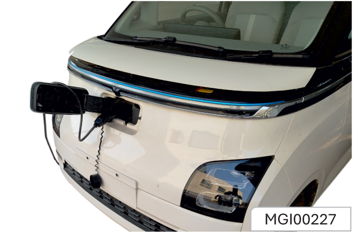
Charging with AC Supply:
- Open the vehicle charging port
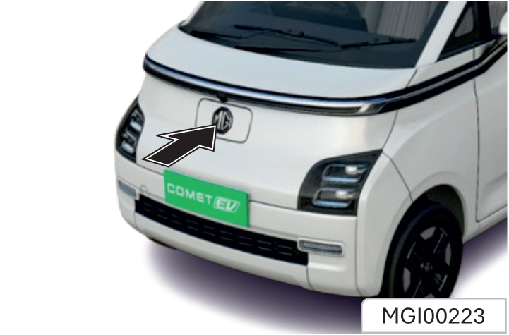
As shown in the figure, press the right side of MG logo to make the charging port door pop open
Open the charging cap, as shown in the figure.
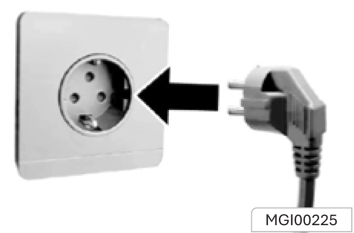
- Insert the plug into the power socket.
Insert the plug into a 230V (≥16A) grounded household AC power socket. Please select a socket with power > 3.6 KW and use it exclusively for charging.
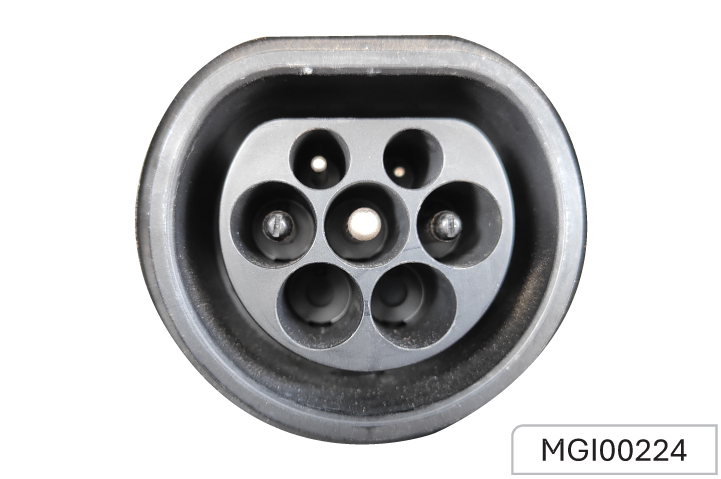
- Insert the charger plug into the charging port.
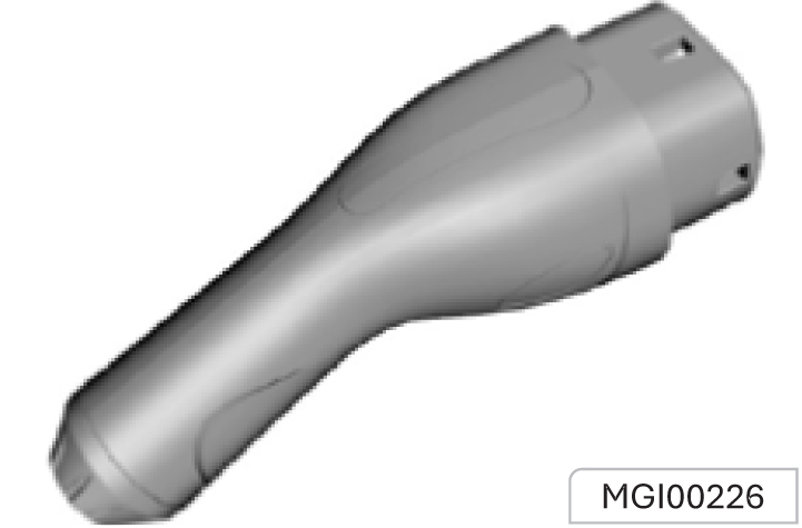
Remove the charger plug cap
Insert the charger plug into the charging port until you hear a “click”. Insert the charging gun correctly, and then the green indicator light flashes.
- Green light 1 - first green light is for POWER ON and it will continuously remains ON while charging
- Green light 2 (center)- will blink (in green colour) during charging, will remain ON when SOC reaches 100%.
- Red light- for malfunctioning During charging, the green indicator light flashes. In case of any malfunction, the red indicator light is always on or flashing.
- Pull out the charger plug after charging.
Insert the charger plug into the charging port. Switch off the supply, pull out the charging gun and fit the charging gun cover, charging cap and charging port door in place.
Smart Charging
The 12V battery SOC is constantly monitored, when the Start/Stop switch is in the OFF position it is possible, under certain conditions, that the HV battery will automatically charge the 12V battery to ensure the vehicle starts. This function will activate and switch off automatically.
The system will suspend intelligent charging if a fault is present, when starting or the vehicle is being charged by an external device. The driving range will be reduced after intelligent charging. The intelligent charging function is suspended when the high voltage battery is in a low SOC.
Charging Precautions
- Park the vehicle in a ventilated place. Do not stay in the vehicle.
- In case of a power outage during charging at home, the charging system will continue to charge the vehicle after power restoration.
- When charging at the charging station, follow its operation requirements and wait in a safe area.
- Before driving, make sure that the charging gun is pulled out, the charging cable is put away, and the charging port is closed.
- It is normal that the predicted time to full charge may vary to some extent with different ambient temperatures and power capacities. At a low ambient temperature, the charging efficiency decreases and the charging time is extended.
Cell Balancing & equalization
Cell balancing and equalization, as well as state of charge (SoC) calibration, occur during charging, particularly when the SoC is above 90%. This results in longer charging times when exceeding 90%. It is recommended to allow the vehicle to charge to 100% SoC before ending the charging session.
Before charging, check the charging port and the connector port of the charging plug for any water or foreign matter. If any, charging is not allowed. Otherwise, it may lead to short circuit or electric shock, resulting in personal injury and property loss. Do not touch the metal parts of plugs and other connectors when charging. Water conducts electricity. During charging, do not touch the charging cable and plug with wet hands, and do not charge the vehicle in a wet place otherwise, you may get an electric shock. In case of any abnormal smell or smoke during charging, stop charging immediately and contact the service center in time. Do not charge the vehicle in thunder and lightning conditions, or in the open air in rainy days. Otherwise, it may damage the charging equipment, or cause lightning strike and electric shock.
Several months of storage of the vehicle:
- Clean and wax the vehicle.
- Check the wax coating of front compartment and the underbody
- Clean and protect the rubber seal.
- Drain the windshield washing fluid reservoir.
- Adjust the tyre pressure according to the specified value under full load.
- Charge the traction battery to about 60%.
- Close all doors and lock the vehicle
- Check that the handbrake is pulled up completely and the vehicle will not move.
- Disconnect the clip from the vehicle battery negative terminal. Pay attention to that all systems are out of service at this time, e.g., theft alarm system.
When the vehicle is to be put back into service
- Connect the clip to the vehicle battery negative terminal. Enable the electronic device of power window
- Check the tyre pressure.
- Fill up the windshield washing fluid reservoir.
- Check the coolant level.
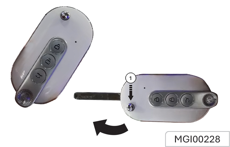
Type 1- Folding Key*
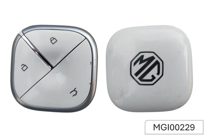
Type-2 - Intelligent Key*
- Please keep the spare key* in a safe place - not in the car!
- It is recommended that spare keys* are not kept on the same key* ring, since this may cause interference and prevent correct key* recognition and therefore prevent the correct operation of the vehicle power system.
- The smart key* contains delicate circuits and must be protected from impact and water damage, high temperature and humidity, direct sunlight and the effects of solvents, waxes and abrasive cleaners. Different models may be provided with different keys. Please refer to real vehicles. If your key is a folding key, press the release button 1 to automatically eject the mechanical key.
The smart key functionality may be altered or it may cause malfunction under following conditions:
- the frequency band from the smart key may be mixed with a different frequency (from engine operation, door lock function, electronic systems, woofer, mobile phones, portable wired/ wireless charger, heating device, electronic power banks, e-cigarettes, etc.)
- If the smart key is near your mobile phone , its signal may be blocked by the normal operation of the phone.
- Do not place your smart key and mobile phone in the same pocket of jackets/pants.
- Do not place smart key over the wireless charger of the vehicle.
Keep smart key away from electromagnetic materials that blocks electromagnetic waves to the key surface.
Replacing the Key Battery
Battery Replacement Inside the key remote control, there is a lithium battery whose service life is 2 years generally. When the remote control distance is shortened gradually (i.e. must get closer to the vehicle), it indicates a low battery. The key battery cannot be charged. After the battery runs out, please go to the JSW MG Authorised Service Center to have the battery changed.
Door Lock Remote Control System
The effective distance of remote control is about 10m without shielding. The remote control range may be different in different environments.
- Remote lock button. After the doors are closed, press the remote control locking button once to lock all doors. The hazard warning lamp flashes twice to enter the anti-theft state.
- Remote unlock button. Press the remote control unlocking button once to unlock all doors. The hazard warning lamp flashes once, and the anti-theft state is released.
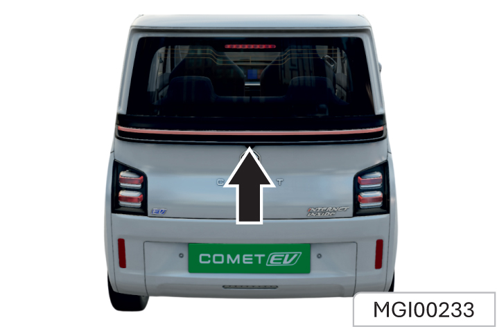
- Tailgate opening button. Press tailgate opening button for about 2s to unlock the tailgate.
Warning Sound
If the door fails to lock after the remote locking button is pressed, the vehicle will horn and/or flash a hazard warning lamp
Specific situations include:
- A door/some doors not closed (including tailgate);
- The door lock is under thermal protection;
- The ignition switch is not at LOCK position;
- The keyless entry system (if configured) detects a legal key in the vehicle.
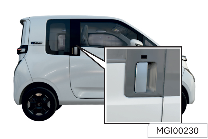
Press the button on the front door handle to lock or unlock the door. The system operates when:
- The ignition switch is at LOCK position;
- The key is within the PEPS sensing range (1.2m);
- All doors are closed;
- The key is not in the vehicle.
The system is automaticallyactivated when the key is removed from the ignition.
Features of the Immobiliser System
- Prevents the vehicle being started by anyone not in possession of the correct vehicle key
- The vehicle is automatically protected after the key is removed from the ignition. At every ignition ON, if the vehicle does not recognise the correct key code, the engine check lamp will illuminate/blink and the engine cannot be started
- The vehicle will not be protected until the key has been taken out of the ignition
Locking and Unlocking from Outside the Vehicle
To open doors from inside or outside, unlock the doors first, and pull the external or internal door handles.
When you leave the vehicle unattended, you must lock all doors and take the key with you. If the doors are unlocked, the vehicle may be stolen.
Locking and Unlocking from Inside the Vehicle
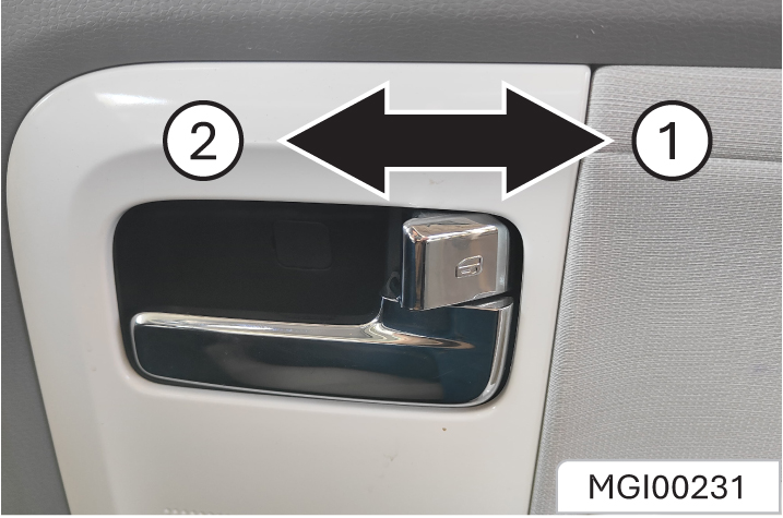
As shown in the figure, there is a
door lock button on each door. Press the door lock button forward to lock, and pull it backward to unlock. The door lock button on the driver-side door can also be used as the central door lock.
Antitheft Detent Warning System
1. Arming of Vehicle
Once all the doors are closed and locked with remote by pressing lock button, Theft Detent warning system would get activated.
2. Theft Detent Trigger
If any door remains open and the vehicle is locked using the key, the system will alert the user by honking twice and flashing the hazard lamps three times.
Once the alarm is triggered, it can be disabled by pressing unlock button on remote or switching on the Ignition by using valid key.
Thermal Protection
The Door lock mechanism does not respond to remote/CDL requests. If you try to lock or unlock the door more than 8 times in 20 seconds, it will stop working for 20 seconds. After that, it will work again.
Tailgate Opening from Inside the Trunk
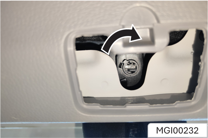
If the tailgate fails to open in this way, it can still be opened by the following steps:
Open the tailgate lock trim cover to see the slotted knob. Turn the knob clockwise with a straight screwdriver to open the trunk.
Tailgate Keyless Unlocking/ Locking*
Press the button on the tailgate to lock or unlock the tailgate. The system operates when:
- The ignition switch is at LOCK position;
- The key is within the PEPS sensing range (1.2m);
- All doors are closed;
- The key is not in the vehicle
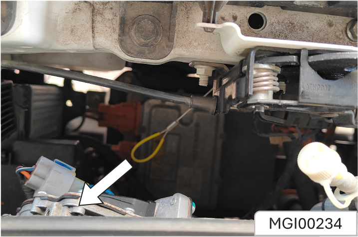
There is a cable given inside the front compartment hood, by pulling it together with charging gun, the Gun can be extracted from the vehicle during any malfunctioning or emergency situations.
Check the interior, exterior and front compartment regularly to keep the vehicle safe and reliable.
Exterior
Tyres
- Inflate correctly. See “Wheels and Tyres” in this chapter
- There is no crack on tyre wall or tyre tread.
- There are no foreign matters in tread pattern.
Lights
- Include all driving lamps, headlamps, tail lamps, turn signal lamps, brake lamps and fog lamps.
Windscreen Wipers
- Check the state of wiper arms and blades.
Interior
Steering
- Check whether the steering wheel is too loose (free stroke).
Parking Brake
- Ensure the stroke of parking brake lever is appropriate.
Instrument Panel
- Check whether all instruments, control buttons and warning lamps are functioning normally
Rearview Mirror
- Ensure the reflecting surface of rearview mirror is in good state and clean.
- Check whether all rearview mirrors can be readjusted.
Control
- Check the brake pedal and clutch pedal for appropriate s
Front Compartment
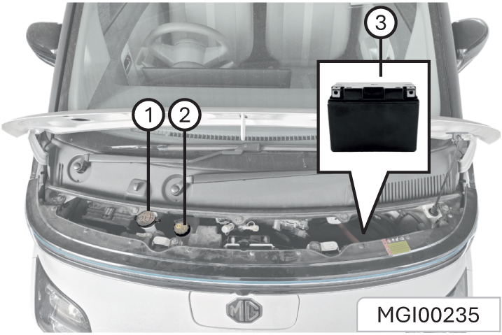
- Windshield washing fluid reservoir
- Brake fluid reservoir
- 12V battery
12V Battery
Warning notice on battery:
 Wear glasses!
 Wear protective gloves and glasses
since battery acid is highly corrosive!
Wear protective gloves and glasses
since battery acid is highly corrosive!
 Open flames, electric sparks, strong
light and smoking are prohibited!
Open flames, electric sparks, strong
light and smoking are prohibited!
 Explosive mixed gas may be produced
during battery charging!
Explosive mixed gas may be produced
during battery charging!
 Children should be kept away from acid
and battery!
Children should be kept away from acid
and battery!
Your vehicle is equipped with a JSW MG authorized genuine battery, located in the front compartment. According to current load condition and battery status, the system may limit the power of some electrical appliances. Please ensure the vehicle is placed in READY mode as soon as possible to charge the battery.
Best Battery Service
- Keep the battery top clean and dry.
- Keep the terminals and connections clean, tight, and coated with petroleum jelly or terminal grease.
- Rinse any spilled electrolyte from the battery immediately with a solution of water and baking soda.
- Keep the battery securely mounted.
- Tighten loose terminals and hold down clamp nuts only enough to keep the battery firmly in place.
- Tightening excessively may damage the battery terminals.
To avoid battery discharge, please turn off the ignition switch when leaving the vehicle. Do not leave the power tailgate open for a long period of time. This may drain the battery.
Unauthorized Electrical Devices
The vehicle can detect selfdischarge of the battery due to over-current that is generated by unauthorized electrical devices such as dashboard camera (dash cam) mounting during parking. If the warning continues even after external electrical devices are removed, have your vehicle inspected by a professional workshop. Accessories- All accessories connected to the battery powered outlets should be removed or turned off when the vehicle is not in use to protect the battery against discharge.
It is advisable to avoid use of any 12V vehicle systems & accessories such as Power tailgate, Sound system, Interior & Exterior lamps, AC Slower, etc when engine is switched off. This may caution 12V battery to drain faster.
Risk of injury, corrosion, accident and fire exists when operating on vehicle battery and electrical appliance! Wear protective glasses. Prevent acidic or lead particles from falling into eyes, on skin or clothes. Wear protective gloves and glasses since battery acid is highly corrosive! The battery can not be turned over because the acid may flow out of the air vent. If the acid splashes into eyes, wash with clean water for a few minutes, then go to see a doctor immediately. If the acid splashes on skin or clothes, immediately neutralize it with rich soap solution and rinse with plenty of water. If you mistakenly drink acid, go to see a doctor immediately
Open flames, electric sparks, strong light and smoking are prohibited! Avoid sparking when handling cables and electrical equipment and removing electrostatic loads. Battery electrode must not be shortcircuited because sparks with high energy pose a risk of injury. A battery generates hydrogen gas which is flammable and explosive. Keep any flame or spark away from the vent holes. Battery charging may produce explosive mixed gas, you must ensure that the battery air vent is open to successfully discharge the gas. The battery should be located in a well ventilated space during charging. Children should be kept away from acid and battery. Turn off the engine, ignition switch and all the electrical appliances before working on electrical appliances. Remove the battery negative cable. Turn off the lamp in bulb replacement. Please pay attention to the polarity of power supply. check if the polarity of power supply matches before energizing. Each energizing period should not be less them 5 seconds, to avoid frequent or fast on and off operation. Turn off all the electrical appliances before energizing the battery again. First connect the positive cable, then the negative one. Do not connect the wrong cable. Risk of fire!
Unauthorized removal and installation of battery are prohibited, because in some cases, this operation will lead to serious damage to the battery and fuse box. Please contact Service Dealer. Do not disconnect the battery when the ignition switch is on or the engine is running, otherwise it may damage the electrical appliances (electrical components). To prevent the battery case from being exposed to ultraviolet light, do not expose the battery to sunlight. Never attempt to dismantle a battery, they are sealed units. While removing the battery, always disconnect the negative terminal first. And while installing the battery, ensure the negative terminal is connected last. If the battery has been disconnected or a new battery has been installed, the preset radio (if equipped) stations will get reset, once the battery is reconnected.
Battery Specifications*
| Vehicle Type | Diesel |
| Rating | 12V 32Ah |
| Technology1 | Lead Acid |
| CCA | 270 A |
| Dimension | 197(L) x 129(W) x 227(H) |
| Supplier | Exide |
Car Parking Period
If the vehicle is to be parked for an extended period of time, the static current electrical appliance (like clock, security devices) will drain the battery, and the battery has to be recharged. To avoid such case, charge the battery or disconnect the battery negative cable during the vehicle parking.
It is recommended to ensure the vehicle is placed in READY mode for half an hour every week to help extend the service life of the battery. If the vehicle is stored for more than 1 month, remove the negative terminal from the battery. Make sure that the vehicle power system has been turned off before connecting or disconnecting the negative terminal.
Always turn off the ignition switch when parking, otherwise, it will greatly reduce the parking time.
Battery Charge with Ground Equipment
Don’t charge the frozen battery for the risk of explosion. Even if the battery has been unfrozen, battery acid may still overflow, resulting in corrosion damage. The frozen battery must be replaced.
Turn off the ignition switch and all electrical appliances before charging. If the vehicle has been stored for an extended period of time, and can not be started due to battery undercharge (general terminal voltage ≤ 12V), the battery must be removed from the vehicle and charged with ground equipment (operating in accordance with the charging device manufacturer’s instructions). When charging with a low current (such as a small charging device), generally it is not required to remove the battery connecting cables. But you must pay attention to the instructions
given by the charging equipment manufacturer. Before the quick charge, that is, before the high current charge, you must remove two connecting cables.
Please pay attention to the warnings & instructions for battery before working on it. When charging, the power supply of charging device can be switched on only after the charging device electrode chuck clipped to the battery electrode as specified. After charging, first turn off the charging device, unplug the power cord, and then remove the electrode chuck of charging device from the battery.
- Keep children away from the battery, battery acid and charging devices.
- The battery can only be charged in an ventilated space. Smoking, open flame and electrical sparks are prohibited, because explosive mixed gas will be produced during battery charging!
- To protect your eyes and face, please stay away from the battery.
- If the acid splashes into eyes or on skins, rinse with clean water for a few minutes and go to see a doctor immediately.
- Battery fast charging is dangerous and should be performed by Service Dealer, because it requires specialized charging equipment and knowledge
- Replace the frozen or unfrozen battery. Cracking may occur on the battery case because of freezing. Battery acid may leak and damage the vehicle.

Checking the Electrolyte Level Check the electrolyte level and specific gravity at specific PMS intervals. Check proper electrolyte levels for all the cells. If the level is below the lower marker, add distilled water until the level reaches the upper marker.
Adding distilled water:
- Remove the vent plugs
- Add distilled water to all the cells that require the fluid and secure the plugs properly.
Battery Removal
Turn off the ignition switch and all electrical appliance before removing the battery. To remove the battery, you should first remove the negative cable, next the positive cable, and then remove bolts on the battery retaining bracket , finally remove the battery.
Battery Replacement
Please go to an MG Authorised Repairer to remove and refit the battery. Please note that the ignition switch and the electrical appliance have been turned off when installing the battery.
Only fit MG recommended battery while replacement to maintain the correct vehicle functionality. Battery needs to dimensionally OK, to avoid terminals fouling with Battery Tray.
 The used battery should not be
discarded at will, for it is harmful
to the environment. It must be
recycled by approved agencies.
Please consult an MG Authorised
Service center for more details.
The used battery should not be
discarded at will, for it is harmful
to the environment. It must be
recycled by approved agencies.
Please consult an MG Authorised
Service center for more details.
Battery Installation
Turn off the ignition switch and all electrical appliance before removing the battery. Place the battery in the mounting position and secure it with battery bracket. Secure the positive cable then the negative one, then energize the battery.
To avoid battery discharge, please turn off the ignition switch when leaving the vehicle.
The JSW MG Motor shall not be liable/responsible for any damages/injuries, including consequential damages/injuries, resulting due to fitment of non OEM approved batteries.
Brake Fluid
Add Brake Fluid
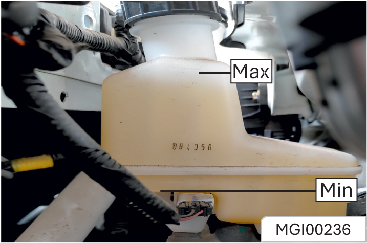
- Thoroughly wipe off the dirt around the reservoir filler cap.
- Open the filler cap
- Fill the brake fluid recommended by MG to the MAX mark of the fluid reservoir. Be careful not to spill the fluid on the paint surface. In case of spilling on the paint surface, wash the area with cold water immediately.
- Re-install the reservoir filler cap.
Before opening the oil filler cap, clean the area around the brake fluid reservoir filler cap. Contamination of the brake fluid system will affect the system performance, resulting in costly repairs.
Windshield Washing Fluid
Before driving, be sure that the washing fluid reservoir contains sufficient specified washing fluid. In cold weather, the windshield washing fluid reservoir cannot be overfilled. Washing fluid will swell under low temperature due to freezing. An overfull container has no enough space for expansion, thus resulting in damages.
Fuse
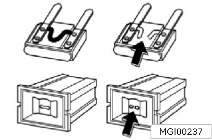
Fuse Replacement:
- Open the fuse box cover
- Identify damaged fuses by finding out blown fuses.
- Use a fuse extractor to remove the blown fuses.
- Identify the cause of the fuse blowout and rectify the issue.
- Install new fuses that meet the required rated current specifications.
Fuse Box
Front Compartment Fuse Box
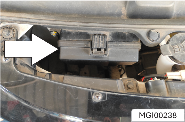
The fuse box is located at the right of the front compartment.
Do not use a conductive tool to remove the blown fuse. The fuse extractor must be used. The use of metal and other electric conductors may cause a short circuit, damage the electrical system or cause a fire, resulting in serious personal injury. The use of fuse substitutes or the fuse with an incorrect type and rated value may damage the electrical system or cause a fire. Be sure to use a fuse whose type and rated current meet the requirements. Otherwise, it may cause personal injury and damage the vehicle and other properties
Lamp Fogging
When the temperature is low or the air is humid, you may see mist in the lamps. After turning on the lamps, the mist will disappear in a short time. This is weather related and does not require maintenance. If the mist still exists after the lamp is turned on, please contact the service center for maintenance.
Wheels and Tyres
Original tyres guarantee optimum matching of riding comfort, tread life and performance.
Be sure to use wheels and tyres of specified specifications. The use of wheels and/or tyres of other specifications may result in abnormal operation of ABS and other relevant components and even cause collision accidents. Please consult the After-Sales Service Center before replacing original tyres or wheels. otherwise, it may cause personal injury and damage the vehicle or other properties.
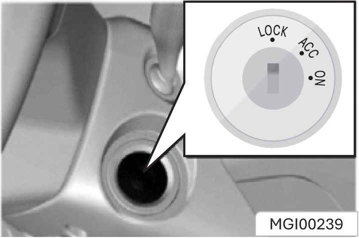
The power switch is located below the right side of the steering wheel and has the following working positions:
LOCK, ACC and ON
- LOCK
This position is for power turning off and steering wheel locking. Only when you turn the power switch to this position can you pull out the key. Lock the steering wheel. Remove the key and turn the steering wheel till the steering wheel is locked. If you cannot turn the key when unlocking the steering wheel, you can gently turn the steering wheel to right/left for one thing and turn the key for another.
- ACC
- ON
This position is for power-on of some electrical equipment, such as the audio system. The instrument panel illuminates when the power switch is turned to this position. When the key is turned to ACC, check whether the warning lamps and indicators on the instrument panel are on and off normally.
Do not keep the key at “ACC” for a long time. Otherwise, the power of 12V battery may be excessively consumed.
This position is for power on of all electrical accessories except HV electrical appliances. Only the power switch is at the “ON” position can the vehicle enter the READY state.
If it is not necessary to start the vehicle, please do not keep the key at “ON” for a long time. Otherwise, the 12V battery may be excessively consumed.
“READY” State (Start State)
When the vehicle enters the “READY” state, all the HV working circuits will be turned on, and the
driving motor will be ready to drive in gear. The “READY” state is similar to the starting state of an internal combustion engine vehicle. Only when the vehicle enters the “READY” state can you engage the gear and turn on the A/C for cooling or heating.
How to Enter “READY” State:
- Turn the power switch to “ON” first
- Then press the brake pedal until the READY indicator on the instrument panel illuminates.
After entering the READY state, the vehicle will remain in this state until you turn off the power switch to “ACC” or “LOCK”. For keyless models, press the brake pedal gently twice to enter the READY state.
How to Exit “READY” State:
Turn off the power switch to “ACC” or “LOCK”. After the vehicle exits from the “READY” state, the driving motor will exit from the working state, and the vehicle cannot be engaged in gear or run. For keyless models, you can lock the vehicle after getting off, and the whole system will be turned off. Or
you can press the OFF button below the steering wheel to exit.
Do not use emergency button excessively. Use only in case of emergency.
Preparation Before Entering “READY” State:
- Check that the handbrake has been pulled.
- Ensure that no barriers exist around the vehicle
- Ensure that all windows and doors are clean and transparent.
- Check whether the tyre conditions and the inflation pressure are proper and whether foreign matters exist.
- Ensure that seats and rearview mirrors are at proper positions. Adjust them if necessary.
- Fasten the seat belt and ask passengers to fasten seat belts.
- Release the handbrake before the vehicle starts.
If Vehicle Cannot Enter “READY” State
If the READY indicator on the instrument panel does not
illuminate, it indicates that the vehicle has not entered the READY state. Please check whether the power switch is at the “ON” position and whether the brake pedal has been pressed. If there is no display on the instrument panel when the power switch is at the “ON” or “ACC” position, the 12V battery may not have insufficient power. Therefore, charge the 12V battery first. It is suggested to contact the Aftersales Service Center for solution.
If the vehicle is not at the “READY” state, please do not use the audio system, lamps, A/C or other electrical equipment for a long time. When leaving the vehicle, please also shut down the electric equipment. Otherwise, the 12V battery will run out, causing the instrument panel unable to display and the vehicle will not enter the READY state.
Parking
- Before getting off the vehicle, pull handbrake turn the power switch to “LOCK” and pull out the key. Turn the steering wheel till the steering wheel is locked.
- When parking on a ramp, pull the parking brake as tightly as possible, while pressing the brake pedal.
- When parking the vehicle on one uphill ramp, turn the front wheels away from the road shoulder. When parking the vehicle on one downhill ramp, turn the front wheels towards the road shoulder
Do not park and drive the vehicle on inflammable such as straw and hay. If such inflammables cannot be avoided, park the vehicle to check and confirm that these inflammables are not attached at the chassis after the vehicle passes the inflammables. Otherwise, these inflammables may be ignited by hightemperature components on the chassis, and thus a fire accident can be caused.
Gearshift Knob
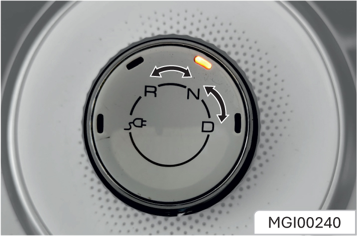
Turn the knob to shift gears according to the marks on the knob. You can see the current gear in the gear display area on the instrument panel. The backlight of the corresponding gear position on the knob will also go on. Only in the READY state can you drive in gear. When engaging in D or R position, you must first depress the brake pedal; otherwise you cannot engage into gear.
: Charge
R : Reverse
N : Neutral
D : Drive
The vehicle is equipped with economy, normal and sports driving modes. Press the E/S button on the instrument panel to change the driving mode. The driving mode will
affect the acceleration performance. Under the economy mode, the vehicle speed will be limited to 80 km/h.
Do not allow children to operate the gearshift knob to avoid accidental start of the vehicle. When the gear position is in R, if the gearshift knob continues to be turned left, the gear position remains in R. When the gear position is in D, if the knob continues to be turned right, the gear position remains in D.
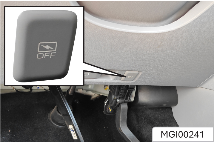
If the vehicle is equipped with an emergency power-off button, this button can be used to cut off the power supply in an emergency. When the vehicle speed is less than 2 km/h, press this button to
shut down the vehicle immediately. When the vehicle speed exceeds 2 km/h, press this button for 5s or 3 consecutive times within 2s, and the power supply will be switched to ACC state. When the vehicle speed is less than 2 km/h, the state will be switched from ACC to OFF.
TPMS
The TPMS indicator illuminates when the vehicle tyre pressure is low. When the TPMS fails, the indicator will flash for 60 seconds and then is normally on. The vehicle is equipped with an indirect TPMS. After each inflation to adjust the tyre pressure or replace the tyre, the TPMS (ordinary type) must be reset by pressing the TPMS button on the right side of the instrument panel for 2s. For intelligent type, you can set the vehicle through the menu in the multimedia host.
Internet Of Vehicles*
You can remotely control the vehicle, view the vehicle status, and perform voice interaction through the intelligent network system of the vehicle. You need to download and install “MG iSMART” application from Google play Store for Android operating system or from App Store for IOS operating system, then register and connect it to the vehicle
Vehicle Maintenance Accessories and Vehicle Retrofitting
We recommend the use of original spare parts and parts specially matched with this vehicle approved by our company. We do not recommend the use of other products, even if they meet the specified requirements or are otherwise approved. Without the approval of MG, do not retrofit the electrical system.
Do not retrofit the vehicle. Retrofitting may affect the vehicle performance, durability and safety. Any problems caused by retrofitting are not within the scope of warranty. The Company will not bear corresponding responsibilities for the safety problems caused by retrofitting.
BEV has less noise during driving, and thus the low speed pedestrian warning system onboard can play a good role in pedestrian alerting. When the vehicle runs at a speed of 0 ~ 30 km/h or backs up, the warning system is working. The vehicle’s pedestrian warning device will make a buzzing sound similar to that of the engine or a beeping sound similar to that of the reversing sensor.
The warning sound volume of the low- speed pedestrian warning device is gradual. When the vehicle speed is close to 0 or 30 km/h, the sound will be the minimum, and when the vehicle speed is 15~20 km/h, the warning sound will reach the maximum. Battery electric vehicle has less noise during driving, and thus the low-speed pedestrian warning system on-board can play a good role in pedestrian alerting. Only when there are no pedestrians in a short distance and the surrounding environment obviously does not require a warning tone can the
When the vehicle power is below 96% and the vehicle speed is high, release the accelerator pedal or step on the brake pedal, and when the system judges that the conditions for energy recovery are met, the vehicle will recover energy. The mechanical energy during driving will be converted into electric energy and then stored in the traction battery to increase the endurance mileage.
When the energy recovery system is working, the traction battery and wheel symbols in the car image on the left side of the instrument panel display green, the power is displayed as negative, and the energy recovery indicator goes on.
Limitations of energy recovery:
- No energy recovery is required when the vehicle power is more than 95%.
- No energy recovery is required below 0°C.
- When ABS or ESC* fails, energy recovery will not be carried out.
- In “S” (Sports) mode, no energy recovery is available at a vehicle speed less than 5 km/h. In “E” (“Economy”) mode and standard mode, no energy recovery is available at a speed less than 8 km/h. Under some other conditions other than the above, the energy recovery indicator on the instrument panel may not light up, but there is still energy recovery. In this case, the energy recovery power is small.
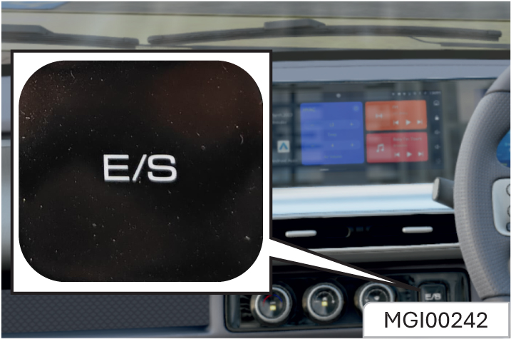
- Long press E/S button (~3s) to switch energy recovery level – light, normal & heavy. If equipped, it can be set from the infotainment screen also.
- Gently press E/S button to switch driving modes – ECO, NORMAL & SPORT.
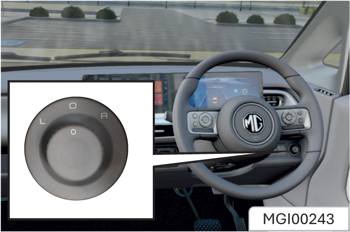
The exterior rearview mirror can be adjusted through the electric adjustment switch on the right side of the instrument panel. The adjustment steps are as follows:
- Select the rearview mirror to be adjusted. Turn the rocker to the “L” (left) or “R” (right) on the selector switch to display the left or right rearview mirror to be adjusted
- Toggle the rocker to adjust the selected rearview mirror.
- Turn the rocker to the folding character position folds the exterior rearview mirror. To unfold, turn in the opposite direction.
- If the rocker not at the folding character When the remote locking, passive key locking, or remote locking is activated and successful, the exterior rearview mirrors will automatically fold.
- When the remote unlocking, passive key unlocking, or remote unlocking is activated and successful, the exterior rearview mirrors will automatically unfold.
- If the outside rearview mirror and its spindle are frozen, please remove the freeze first, and use the electric folding/ unfolding functions.
- For example, if the mirror is frozen after the vehicle is parked outdoors for a night in winter, please remove the freeze first, and use the remote control or the passive entry button to unlock doors. Then, the outside rearview mirror will be unfolded smoothly.
- If the freeze is not removed, the freeze will hinder the movement of the rearview mirror, damaging the mirror.
Notes to Electrical Folding of Frozen Outside Rearview Mirror
- When the ignition switch is at the ON position, control the power window with the power window switch on the center console.
- When the key is turned from the ON position to the ACC or LOCK position, or after the key is removed, all windows can still be controlled by the power window switch within 30 seconds.
- In some cases, the one-key up/down of the driver side window may fail, due to such as reconnection after battery replacement.
- When this occurs, the window needs to be initialized by programming. First, lift the driver-side switch until the window is completely closed, hold it for 5 seconds and then release it. At this time, the initialization is completed. If not, please contact the Aftersales Service Center for maintenance.
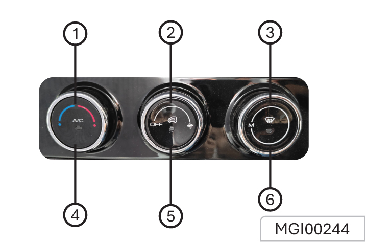
- Temperature control knob
- Fan control knob
- Ventilation mode distribution knob
- A/C button
- Inner/outer circulation button
- Defroster Button
Main System Interface
For details about functional description of the & Navigation system, please refer to the vehicle system Infotainment manual available in the Head Unit User Manual Section.
If the HU is not activated and is not having network connection, a QR code will be displayed, user can scan it and download on the mobile browser.
If HU is activated and have network connected, the User manual QR Code will be downloaded & displayed in the English readable format on the same screen of HU.
Please note that whenever there will be POP up on Infotainment system for Software/FOTA update, please update the HU software for new features and system performance enhancement.
At the same time, always ensure your handheld device (Android & IOS) must be on latest version. To get the latest version , check the software update in Phone settings.
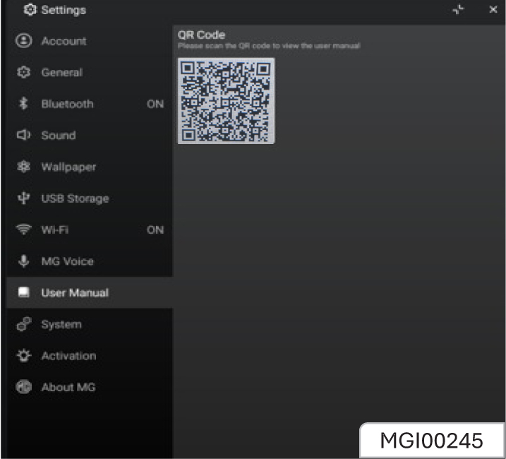
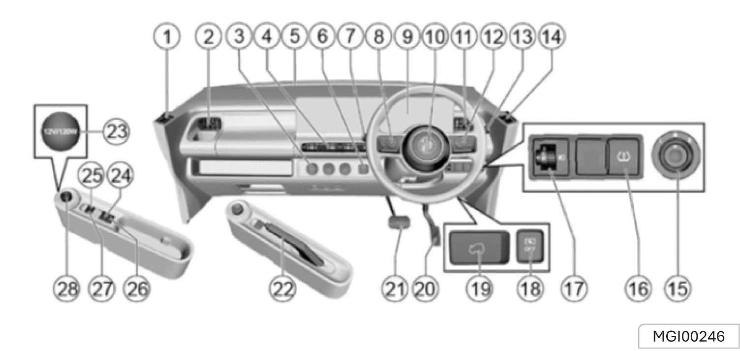
- Left defrosting vent
- Left side air vent
- A/C control knob
- Central air outlet
- Front defrosting vent
- Driving mode button (economy/ normal/sports)
- Wiper combination switch
- Instrument panel combination button
- Instrument panel display
- Horn button/airbag
- Right side air vent
- Audio and entertainment system
- Lamplight combination switch
- Right defrosting vent
- Electric exterior rearview mirror adjusting button
- Tyre pressure monitoring switch
- Headlamp adjustment knob
- OFF button
- Front hood release handle
- Accelerator pedal
- Brake pedal
- Manual parking brake*
- Power socket
- Electronic parking brake switch*
- Right window switch
- AVH switch *
- Left window switch
- Gearshift knob
- Indicator display
- Speedometer and gear display
- Power and range display
- Odometer display
- Vehicle parameter display and setting
- Driving mode display
Type 1*
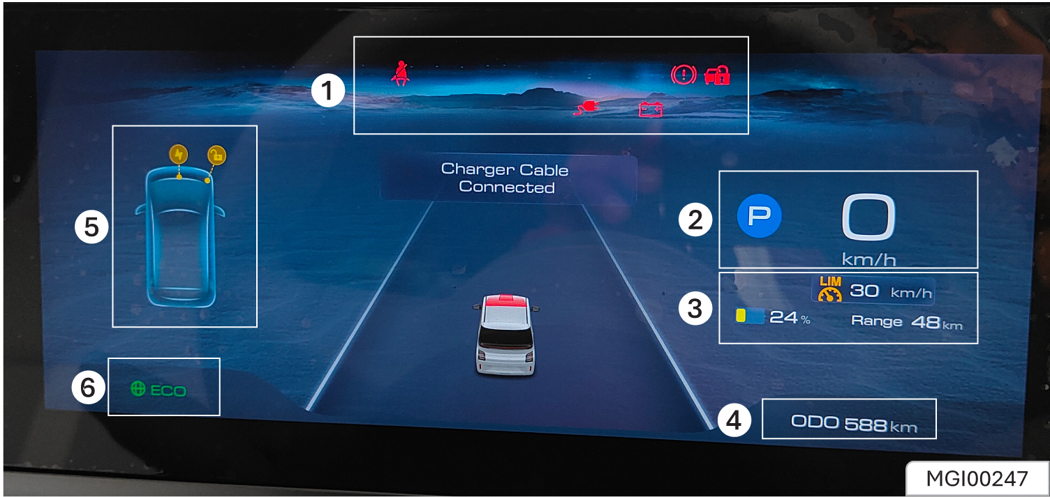
Type 2*
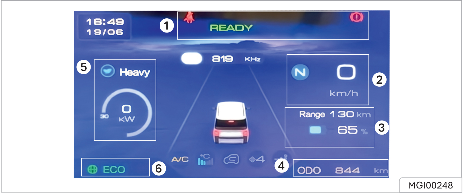
Control Buttons*
These buttons control the display of the vehicle parameters you want to know and select some vehicle settings that can be made.
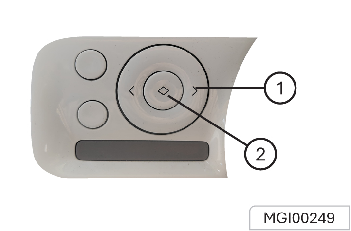
- Left/Right buttons to switch the setting menu on the instrument panel and display vehicle parameters.
- OK button to access the vehicle settings menu on the instrument panel and select from the settings.
Volume Control Buttons on the Steering Wheel
These buttons control the audio system, Bluetooth phone, multimedia system, and WIND*.
Type1*
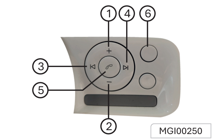
- Volume Increase (+)
- Volume Decrease (-)
- Previous song/ station
- Next song/ station
- BT connection/ call answer & decline
- Media source change and Mute (*)
Type2*
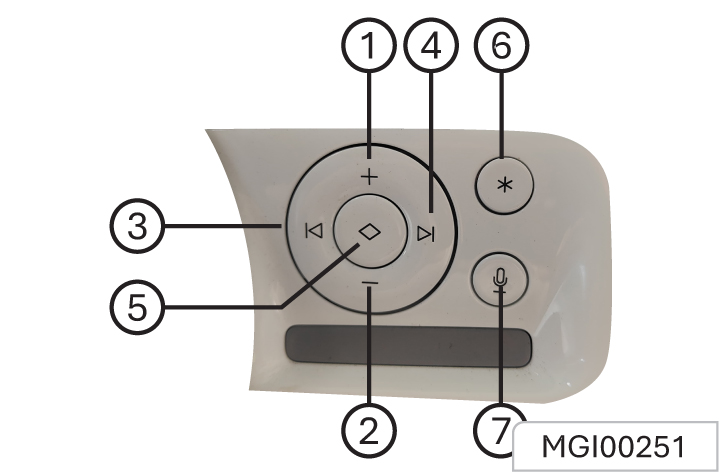
- Volume Increase (+)
- Volume Decrease (-)
- Previous song/ station
- Next song/ station
- Call answer & decline
- Customizable button (*)
- Voice Recognition prompt
When the ignition switch is at the ON position, most of the control indicators will light up briefly as a function test.
Meaning of control indicator color:
Red = danger, important warning
Yellow= warning, information, fault
Green = confirmation on
Blue = confirmation on
Turn Direction / Hazard Warning

When the turning signal lamp flashes, the direction indicator lamp on the corresponding side also flashes. If the hazard warning lamps are operated, both direction indicator lamps will flash together. If either direction indicator lamp in the instrument pack flashes very rapidly, it indicates that the turning signal light on the corresponding side has failed.
Door Open Warning

It indicated that the door is open or not closed tightly.
12V Battery Charging Fault Indication

If this lamp illuminates after starting the vehicle, it indicates that the low-voltage battery charging system has failed. If this lamp flashes, it indicates that the battery power is low, and a prompt message appears in the instrument pack. At this time, the system will restrict or turn off some electrical devices.
Please start the vehicle immediately to charge the battery.
Low Beam Indication

The headlamp low beam is turned on.
High Beam Indication

The headlamp high beam is turned on.
Position Lights

The side lamps are on.
ABS Indication

The ABS has failed.
If an ABS failure occurs while driving, ABS operation will be suspended, but normal braking will still be available.
EPS Indication

If this lamp illuminates, it indicates that the electric power steering system has a general failure and the performance is reduced. Please stop the vehicle as soon as safety permits. If the lamp still illuminates after restarting the vehicle and driving for a short while, please contact a local JSW MG Authorised Repairer for service immediately. If this lamp flashes, it indicates the electric steering column lock has a failure. Please stop the vehicle as soon as safety permits, and turn off the START/STOP Switch.
If this lamp extinguishes after flashing for a while, it indicates that the steering wheel is locked. Please attempt to release the lock by rocking the steering wheel left to right.
Airbag Fault Indication

It indicates that the SRS or the seat belt has failed. As soon as conditions permit, safely stop the vehicle and switch the vehicle power system to the OFF position and contact the JSW MG Authorised Repairer immediately. An SRS or seat belt fault may mean the components may not be deployed in the event of an accident.
Handbrake Indication

The brake system has failed. Please stop the vehicle as soon as safety permits, and turn off the START/STOP Switch.
Anti-theft Authentication Indicator

This indicator illuminates when the door is opened. It goes out after the engine is started.
Seat Belt Unfastened

If this lamp illuminates or flashes, it indicates that the seat belt for the driver or passenger* remains unfastened.
Tyre Pressure Failure Indication

If this warning lamp illuminates, it indicates that a tyre pressure is low. Please check the tyre pressures. If this lamp flashes first and then remains illuminated after a period of time, it indicates the system has detected a fault.
EPB Status Indicator Lamp*

If this lamp illuminates, it indicates that the EPB is enabled
lf this lamp flashes, it indicates that the vehicle is parked on an excessive slope or the EPB system has failed. Please securely park the vehicle on a safe road.
Electronic Parking Brake (EPB) System Malfunction Warning*

The EPB system has detected a fault
AVH- Status Indicator Lamp*

This indicator illuminates when the AVH function works and the vehicle is being parked.
AVH Fault Warning Lamp*

In case of an AVH function module fault or a warning lamp fault, it will be indicated in any of the following ways:
- The lamp does not illuminate when the ignition switch is turned on.
- The lamp does not go out after it illuminates.
- The lamp Illuminates during driving.
Once the AVH fault warning lamp shows the above abnormalities, contact your dealer immediately.
ESC Fault Warning Light*

If this lamp illuminates, it indicates that the stability control system or traction control system has failed.
If this lamp flashes while driving, it indicates that the system is operating to assist the driver.
Stability Control / Traction Control System OFF Warning*

The stability control / traction control system is switched off manually.
READY Indicator

The vehicle is ready for driving.
Charging Status Indication

When the vehicle is connected to an external power supply for charging, this lamp will illuminate and extinguish after charging is completed.
Charging Cable Connection Indication

The vehicle is connected to a charge point.
Energy Recovery Indication

The vehicle is recycling energy
EVP Fault Indication

If the EVP warning light illuminates in below ways, it indicates the EVP fault has occurred:
- EVP light does not illuminate when ignition turns on;
- EVP light keeps illuminating and doesn’t go off after several seconds of ignition turning on;
- EVP light flashes when driving;
- EVP light illuminates when driving;
When EVP fault occurs, it will be less brake vacuum assistant , and you will feel the brake pedal is hard to press down or need more force to press down. If EVP fault is confirmed, must drive very carefully in low and safe speed, and see your dealer as soon as possible. If you are not sure if the car is safe to drive, call your dealer for assistant.
Drive Power Limit Indication

The vehicle power has been reduced.
Motor Overheating Indication

t indicates that the motor has overheated.
Do not continue driving the vehicle. Please stop in a safe area as soon as possible to cool down the motor.
Insulation Fault Indication

It indicates that the vehicle is in danger of electric leakage. Please contact a local JSW MG Authorised Repairer for service immediately.
Front Hood Open Indication

When the front hatch is open or not closed tightly, the warning lamp lights up.
Co-pilot Seat Belt Not Fastened Indication

The seat belt warning lamp illuminates if the passenger does not fasten the seat belt properly after the ignition switch is turned on. The following circumstances will appear unless the driver fastens the seat belt properly
- The seat belt warning lamp keeps illuminated.
- If the vehicle speed exceeds 20 km/h, the warning lamp will flash and the warning buzzer will buzz for a certain time.
Power Battery Thermal Runaway Indication

If the warning lamp lights up, a buzzing alarm sounds in the vehicle and a text message appears on the instrument that says “Vehicle is at risk of fire, exit as soon as possible”. This means the traction battery is overheating and the vehicle is at risk of fire. You should pull over as soon as possible, get out of the vehicle when it stops, withdraw to a safe area and call for help.
Vehicle Fault IndicationW

When the power supply switch is in the ACC position, the warning lamp will be on, and the READY lamp will light up and then go out.
This indicates that the powertrain is normal.
In case of the following circumstances, please consult the nearest Aftersales Service Center for inspection:
- This indicator lamp does not illuminate when the power switch is turned to “ACC”.
- The lamp does not go out after it illuminates
- The warning lamp illuminates, the “READY” indicator lamp turns off, and the vehicle cannot run.
Power Battery Pack Heating Indication

This battery pack heating indicator lamp will illuminate when the vehicle is charged at a low temperature, indicating that the system heats the battery to keep it charged at a safe and reliable temperature.
When the vehicle is fully charged, but the charging power is not disconnected in a low temperature environment, the battery pack
heating indicator lamp will also illuminate, indicating that the system continues to heat the battery rapidly, so that the battery can reach an ideal temperature in the operating environment.
This lamp is a state indicator lamp, not an MIL. It has no influence on driving and will not illuminate during driving. If it illuminates during driving, please contact the nearest JSW MG Authorised Repairer.
Tailgate Open Warning Lamp

When the tailgate is open or not closed tightly, the warning lamp lights up
Low High-Voltage Battery Soc Warning Light

If this lamp illuminates or flashes, it indicates that the high voltage battery charge is low.
Where possible please charge the high voltage battery.
Rear Fog Indication

This indicator illuminates when the rear fog lamp is turned on.
Notes:
ABS: anti-lock brake system
EPS: electronic power steering system
EBD: electronic brakeforce distribution system
EPB: electronic parking brake
AVH: automatic vehicle hold
ESC: electronic stability control system
TPMS: tyre pressure monitoring system
You can learn more about each warning lamp through “My MG app” .
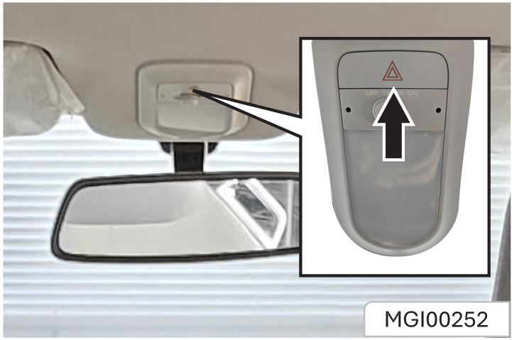
Press to turn on/off the hazard flasher
Headlamp Leveling*
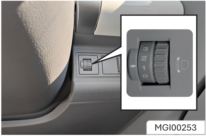
The headlamp leveling knob is located at the right side of the instrument panel.
Please adapt the headlamp illuminating range to the vehicle load so as to acquire the best lighting effect and avoid dazzling. Turn the knob to the desired position:
0 = front seats occupied
1 = all seats occupied
2 = all seats occupied with the trunk loaded
3 = driver’s seat occupied with the trunk Loaded
When the vehicle is turned off, turn the ignition switch to ACC or LOCK, or turn off the headlamp after pulling out the key, and turn the lighting switch control lever toward the steering wheel twice to trigger “Follow Me Home” (The light is delayed off). At this time, if remote locking occurs, the low beam lamp will automatically turn off after a 1-minute delay (The automatic turning off time* can be set on the on-board host.). If the vehicle is not remotely locked, the low beam will turn off automatically 10min later.
Lamp ON Reminder*
If the ignition switch is turned to the LOCK position or the lighting switch is not turned to the OFF position after the key is pulled out, an audible prompt will be given when the driver-side door is opened. The alarm sound stops after the lamp is turned off.
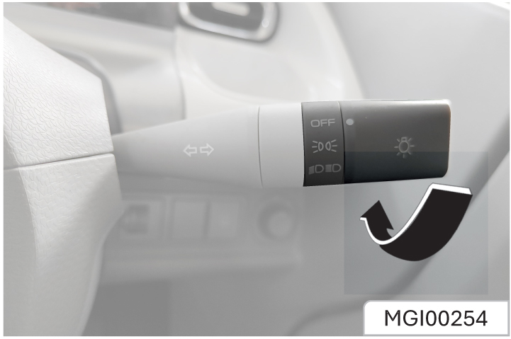
To switch on or off the headlamp, tail lamp and parking lamp, please turn the end of the combination switch control lever
The light switch has 3 positions and they represent different lighting functions:
OFF = All the lamps are turned off.
 = The position lamp, license
plate lamp, instrument panel lamp
and backlighting lamp of all panels
will turn on
= The position lamp, license
plate lamp, instrument panel lamp
and backlighting lamp of all panels
will turn on
 = The low beam lamp and all
lamps mentioned above will turn
on under the precondition that
the ignition switch is turned to ON
position.
= The low beam lamp and all
lamps mentioned above will turn
on under the precondition that
the ignition switch is turned to ON
position.
High Beam
To switch on the headlamp high beam:
Ensure that the ignition switch is in ON position.
The headlamp is in the low beam state.
As shown in the figure, push the combination switch control lever towards the instrument panel.
The headlamp high beam indicator will turn on when the headlamp high beam is turned on. To switch from headlamp high beam to low beam, pull the control lever towards the opposite direction until it returns to the normal position.
Headlamp Flashing
To activate headlamp high beam flashing, please pull the combination switch control lever toward steering wheel and then release it. The control lever will return to the normal position.
Before releasing the control lever, keep the headlamp high beam on.
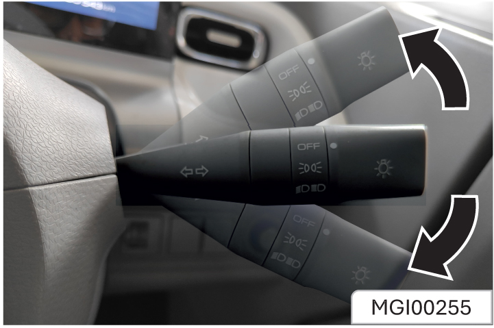
To turn on the turn and lane change signal lamp, the ignition switch must be in ON position.
Control lever upward = left turn signal lamp.
Control lever downward = right turn signal lamp.
After cornering, the turn signal stops automatically and the control lever returns to the normal position.
To change the lane, pull the control lever upward or downward to half position of that of turn signal lamp (not reaching the turn signal lamp position) and hold it. After lane change, release the control lever and it will return to the normal position automatically.
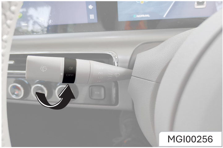
When the low beam of the headlamp is turned on, the rear fog lamp can be turned on by rotating the fog lamp switch on the wiper operating lever.
When the rear fog lamp is turned on, the rear fog lamp indicator on the instrument cluster will turn on.
The rear fog lamp can be turned off by rotating the switch again.
Daytime Running Lamp*
After the vehicle is started, the daytime running lamp will be turned ON when the position lamp is turned to ON position.The Day time running light will go off, when the lighting combination switch control lever is set to OFF condition. When the turn signal is on, the occupied daytime running lamp will automatically turn off.
If the vehicle cannot be started without power, you can borrow the battery of another vehicle to provide power for your vehicle through jump start
Preparation before Jump Start
- Apply the parking brake
- Engage “N”.
- Turn off all electrical accessories
Turn off the audio equipment before jump start of the vehicle. Otherwise, the audio system may be damaged.
When the vehicle is running at a low speed for a long time (such as traffic jam), turn off all unnecessary electrical systems.
Jumper Cable Connection
In case of jump start of the vehicle, connect the jumper cable in the following order:
- Clip one end of the first jumper cable to the positive terminal of the powered battery. (There is a “+” mark on the battery housing or the terminal)
- Clip the other end of the jumper cable to the positive terminal of the dead battery. (There is a “+” mark on the terminal.)
- Clip one end of the second jumper cable to the negative terminal of the powered battery. (There is a “-” mark on the battery housing or the terminal)
- Connect the other end of the cable to the body ground of the vehicle that has no electricity.
- After connection, follow the starting steps to make the vehicle enter the READY state and complete the starting
- To remove the jumper cable carefully in reverse order, remove the negative cable first and then the positive cable.
If towing is necessary, please contact the After-Sales Service Center or a professional towing service company.
Tow your vehicle with a wheel lifter
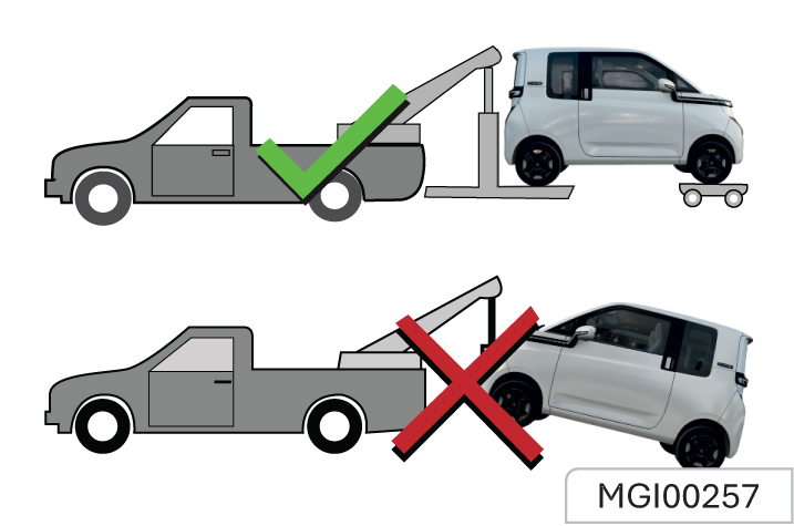
- Turn on the hazard warning flasher.
- Turn the ignition switch to ACC position.
- Engage “N”.
- Release the parking brake.
- Rear wheels must be off the ground when towing.
Tow your vehicle with a flatbed trailer

When towing the vehicle with a platform trailer, turn off the ignition switch and check that the vehicle is firmly attached to the trailer.
Emergency Towing
If the tractor is not available in case of an emergency, it can secure the rope on the front towing hook under the vehicle for temporary vehicle towing
When the vehicle is towed via the front towing hook, only tow rope can be used. Do not use a rigid tow bar.
Your vehicle can only be towed by other vehicles but not used to tow other vehicles.
Front Towing Hook
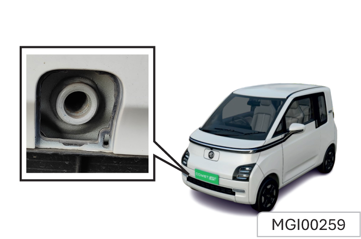
There is a hole cover on the right side of the front bumper of the vehicle. Open it and the fixing hole for hook installation can be seen. Take out the towing hook from the tool bag and install it into the fixing hole. Rotate the towing hook clockwise to tighten it completely and insert a sleeve wrench into the hook hole to assist tightening. Be sure that the towing hook is installed firmly before towing the vehicle. When towing the vehicle, the driver must control steering and braking in the vehicle. After completion of traction, remove the towing hook and close the hole cover, and then put the towing hook back.
The towing speed shall not exceed 30 km/h, and the towing distance shall not exceed 40 km. When longdistance towing is required, it is suggested to contact the After-sales Service Center or a professional towing service company for help.
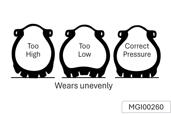
The tyre pressure shall meet provisions of this Manual to ensure optimum matching of driving comfort, safety and driveability
Please refer to “Technical Data” for the correct tyre pressure
When the vehicle is in cool state, check the tyre pressure with an accurate tyre pressure gauge. After check of tyre pressure, tighten the valve core cap.
Check the tyre pressure each time when refuelling or at least every month. Incorrect tyre pressure may:
- Increase tyre wear and vehicle deviation.
- Affect the vehicle manoeuvrability and safety.
- Affect the riding comfort.
- Oil leakage
Excessively low tyre pressure will cause overheat of the tyre, leading to internal damage and layered tread and even tyre burst when driving at a high speed. Even if the tyre pressure was restored later, driving under too low pressure may have damaged the tyre.
Running over sharp objects may damage tyres and wheels.
If you have to run over these objects, please slow down.
Do not touch the curb when parking
Wheel Alignment and tyre Balance
The wheels on your vehicle were aligned and balanced carefully at the factory to give you the longest tyre life and best overall performance. In most cases, you will not need to have your wheels aligned again.
However, if you notice unusual tyre wear or your vehicle pulling one way or the other, the alignment may need to be reset. If you notice your vehicle vibrating when driving on a smooth road, your wheels may need to be rebalanced.
Improper wheel weights can damage your vehicle’s aluminium wheels. Use only approved wheel weights.
Regular Tyre Check
Regular Inspection:
- Appearance damage. These include foreign material, punctures, cuts, cracks, and sidewall projections
- It is also required to inspect the wheel for damage.
Tyre defects including the above defects may lead to vehicle out of control, causing personal injury. In case of damage or abnormal wear of tyre or wheel, please consult the After-Sales Service Center for help.
The vehicle is equipped with radial tyres. MG suggests replacing with radial tyres of the same size, pattern, tread wear, temperature and rated speed.
How to check
Use a good quality tyre pressure gauge to check tyre pressure. You can not tell if your tyres are properly inflated simply by looking at them. Radial tyres may look properly inflated when they are underinflated. Remove the valve cap from the tyre valve stem. Press the tyre gauge firmly onto the valve to get a pressure measurement. If the cold tyre inflation pressure matches the recommended pressure on the tyre
and loading information label, no further adjustment is necessary. If the pressure is low, add air until you reach the recommended pressure. Make sure to put the valve caps back on the valve stems. Without the valve cap, dirt or moisture could get into the valve core and cause air leakage. If a valve cap is missing, install a new one as soon as possible.
If you overfill the tyre, release air by pushing on the metal stem in the centre of the tyre valve. Recheck the tyre pressure with the tyre gauge. Be sure to put the valve caps back on the valve stems. Without the valve cap, dirt or moisture could get into the valve core and cause air leakage. If a valve cap is missing, install a new one as soon as possible
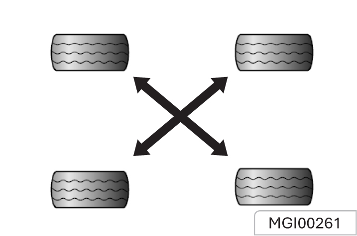
The front tyres and the rear tyres have different functions and therefore have different levels of wear. The front tyres wear faster than the rear tyres. In order to prolong the tyre life and avoid uneven treadwear:
- Conduct tyre rotation as per maintenance regulations in the Manual.
- Keep a proper tyre pressure.
- Check nuts/bolts for tightening.
When rotating tyres, check for uneven wear and damage. Abnormal wear is usually caused by incorrect tyre pressure, improper wheel alignment, out of-balance wheels, severe braking or severe cornering. Look for bumps or bulges in the tread or side of the tyre. Replace the tyre if you find any of these conditions. Replace the tyre if fabric or cord is visible. After rotation, be sure to bring the front and rear tyre pressures to specification and check lug nut tightness.
Information
Tyres that are asymmetrical or directional can only be installed on the wheel in one direction. The outside and inside of an asymmetrical tyre is not easily distinguishable. Pay careful attention to the markings on the sidewalls of the tyres, noting the “outside” marking and the rotating direction before installing them on the vehicle;
Please use the recommended wheels and wheel nuts/bolts. Otherwise, it may lead to the vehicle out of control and cause collision accidents, resulting in personal injury and damage of vehicle or other properties
Tread Wear Indicator
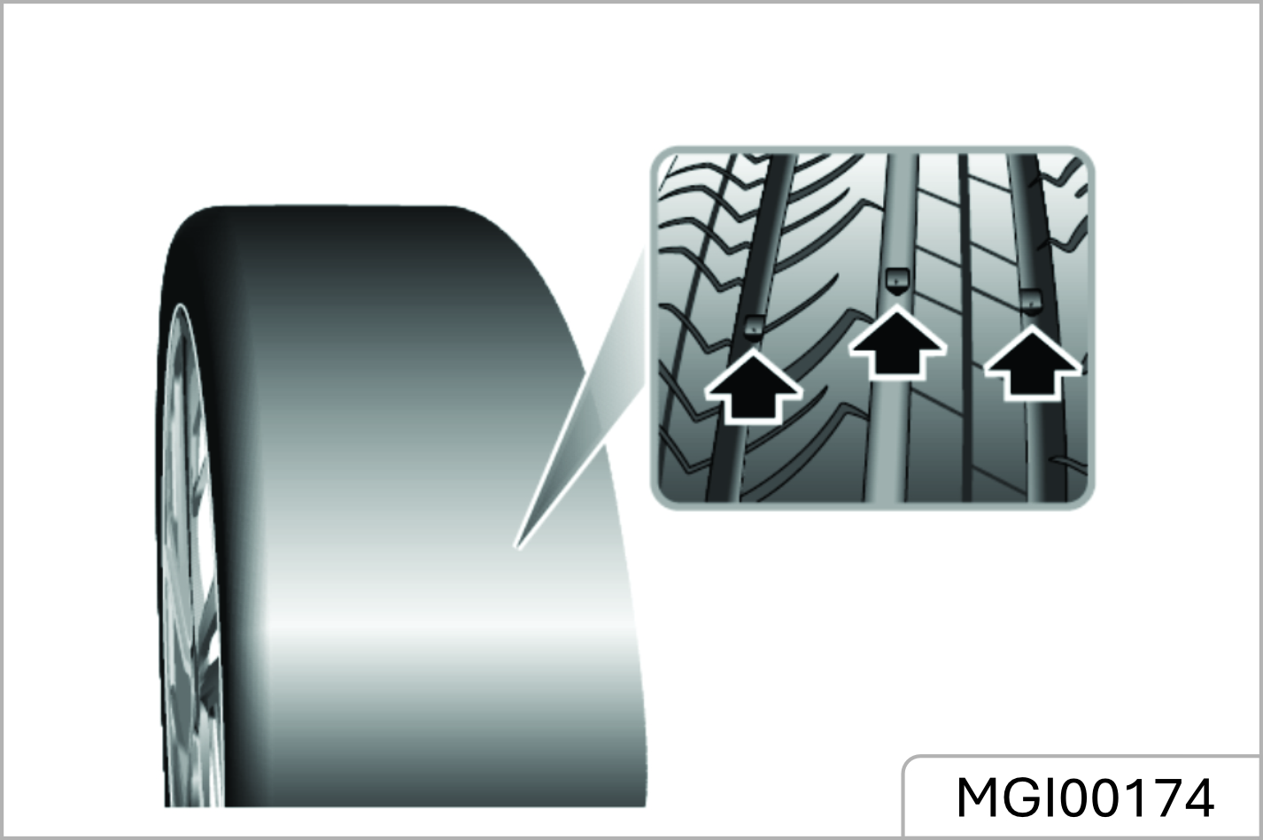
Check the tyre tread depth as per the tread wear indicator regularly. The mark on the tyre wall indicates the position of the tread wear indicator.
The tyre must be replaced when the tread wear indicator appears. When the tread depth is equal to or less than 1.6 mm due to wear, the tread wear indicator will appear between the tread grooves.
Tyre Sidewall Labelling
This information identifies and describes the fundamental characteristics of the tyre and also provides the tyre identification number (TIN) for safety standard certification. The TIN can be used to identify the tyre in case of a recall.
- Manufacturer or brand name Manufacturer or brand name is shown.
- Tyre size designation
A tyre’s sidewall is marked with a tyre size designation. You will need this information when selecting replacement tyres for your car. The following explains what the letters and numbers in the tyre size designation mean.
Example tyre size designation: (These numbers are provided as an example only; your tyre size designator could vary depending on your vehicle.)
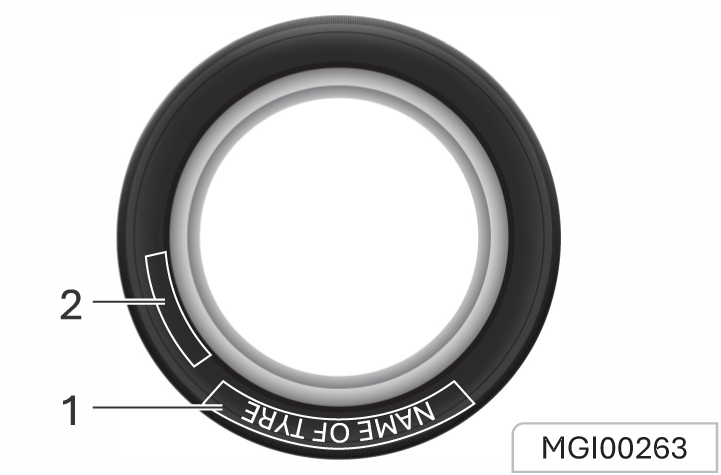
145/70 R12 69S
145 - Tyre width in millimetres.
70 - Aspect ratio. The tyre’s section height as a percentage of its width
R - Tyre construction code (Radial).
12 - Rim diameter in inches.
69 - Load Index, a numerical code associated with the maximum load the tyre can carry
S - Speed Rating Symbol. See the speed rating chart in this section for additional information.
Wheel size designation
Wheels are also marked with important information that you need if you ever have to replace one. The following explains what the letters and numbers in the wheel size designation mean.
Example wheel size designation: 12 X 4.5B
12 - Rim diameter in inches
4.5 - Rim width in inches.
B - Rim contour designation.
Tyre speed ratings
The chart below lists many of the different speed ratings currently being used for passenger vehicle tyres. The speed rating is part of the tyre size designation on the sidewall of the tyre. This symbol corresponds to that tyre’s designed maximum safe operating speed.
| Speed Rating Symbol | Maximum Speed |
|---|---|
| S | 180 km/h (112 mph ) |
| T | 190 km/h (118 mph) |
| H | 210 km/h (130 mph) |
| V | 240 km/h (149 mph) |
| W | 270 km/h (168 mph) |
| Y | 300 km/h (186 mph) |
Cleaning Agent
The manufacturer’s suggestions must be observed when using cleaning agent or other chemical products inside or outside the vehicle.
Do not use dangerous cleaning agent when cleaning the interior and exterior of the vehicle. For example:
- Acetone
- Paint diluent
- Porcelain glaze reducing agent
- Nail polish remover
When cleaning the interior and exterior of the vehicle, the following cleaning agents are prohibited unless special instructions for cleaning stains are included in the fabric cleaning tips:
- Laundry soap
- Bleaching powder
- Reducing agent
Some cleaning agents are toxic, corrosive or flammable. Improper use is very dangerous and may easily cause personal injury or vehicle damage.
Do not use the following materials for cleaning:
- Carbon tetrachloride
- Gasolinet
- Benzene
- Naphtha
When using any cleaning agent or other chemical products inside the vehicle, please open the doors for proper ventilation. To avoid permanent colour change of lightcoloured interior trims, do not allow the easy- Todisco or fabrics to come into contact with the seat liner unless both materials are completely dry. Fabrics with easy-to-discolour materials are:
- Casual clothes
- Dyed denim
- Leather
- Kidskin
Avoid prolonged exposure to cleaning agents and other chemical vapors. Such chemical vapor is extremely dangerous and harmful to the health, especially in limited space without ventilation.
Vehicle Interior Maintenance and Cleaning
Clean the interior and exterior of the vehicle with proper cleaning methods and materials.
Use a vacuum cleaner or a banister brush to remove dust and scum that accumulate on the fabric inside the vehicle frequently. Wipe the vinyl plastics and leather trims regularly with a clean wet cloth. Remove dust, spots or stains on trims with a suitable cleaning agent.
Clean the interior trims of the vehicle with proper cleaning methods and materials. Otherwise, it will produce water spots, watermarks and permanent spots, especially during the first washing. These substances will permanently damage the vehicle.
Seat Belt Maintenance
Keep the seat belts clean and dry. Prevent seat belts from being contaminated by polishing agents, oils and chemical products, especially battery fluid, bleaching powder or dyestuff. These contaminants will reduce the strength of the seat belt material. Check all seat belt parts regularly.Replace any damaged seat belt or part immediately.
The seat belt or related parts that are stretched during the accident must be replaced, even if the damage is not obvious or is not visible. The seat belt for replacement must be new.
JSW MG Motor suggests replacing the whole seat belt assembly after collision. It is not necessary to replace the seat belt after it is checked to be undamaged and normal by the MG Authorised Service Center for solution.
Wiper Blades
Wash in warm soapy water. DO NOT use spirit or solvent based cleaners.
Weather Strips and Rubber Seals
Any weather strips or rubber aperture seals should be treated with suitable materials (silica gel) if they are cleaned using strong detergents, this should avoid any sticking and maintain the service life of the seal.
Glass Surface
Make sure that the window glass is clean, which helps reduce glare and improve vision.
Front Windshield Outside Cleaning
Waxes or other materials on the front windshield and blade may cause the blade to shake when working. Moreover, such foreign matters are not conducive to keeping the front windshield clean. Clean the outside of the front windshield regularly with a non- abrasive cleaning agent. Water does not form water droplets on the clean front windshield.
Vehicle Exterior Maintenance and Cleaning
Exterior
Washing Your Car
In order to preserve the paint finish on your car, please observe the following care points:
- DO NOT use hot water to wash the car.
- DO NOT use detergents or washing up liquid.
- DO NOT use high pressure more than
- 2.5 bar for washing the car body
- In hot weather, DO NOT wash the car in direct sunlight.
- When using a hose, DO NOT aim the water directly at window, door or sunroof seals, or through wheel apertures onto the brake components.
If the car is particularly dirty, use a hose to flush grime and grit from the bodywork, prior to washing. Then, wash the car using cold or lukewarm water containing a good quality wash and wax shampoo. Always use plenty of water to ensure that grit is flushed from the surface and not ground into the paintwork. After washing, rinse the bodywork with clean water and dry off with a chamois leather.
Cleaning the Underside
Flush away accumulations of mud and thoroughly clean those areas where debris can easily collect (wheel arches and panel seams, for example) using pressure hose with pressure not more than 2.5bar. Make sure you do not wash HV battery, charging points & electrical connections– damage to the car’s electronic systems may occur.
- Avoid cleaning the vehicle in direct sunlight
- When cleaning the vehicle in winter avoid spraying water directly onto door locks and panel gaps due to risk of icing.
- Do not use rough sponges or cloth to clean the car, this will damage the paintwork finish.
- When cleaning the headlamps do not use a dry cloth or sponge, use only warm soapy water.
Cleaning with a High Pressure Cleaner
When using high pressure washers, always ensure there is adequate distance between the spray nozzle and any soft materials, decals or rubber seals.
- Please pay attention to the operating instructions of highpressure cleaner.
- y directed at soft parts of the vehicle.
Polishing and Waxing
Regular polishing can remove residues from the surface of the vehicle. After polishing, use highquality car wax for protection
Exterior Bright Metal Parts Protection
Clean the bright metal trims regularly. They are usually washed with water. When waxing the vehicle, please also wax these bright metal parts
Aluminium Wheels and Wheel Trim Cover Cleaning
To maintain the original appearance of the wheel and wheel trim cover (if any), do not allow them to collect dust or brake dust. Clean the wheel / wheel trim cover regularly. Do not use abrasive cleaning agent or brush that may damage the finish paint.
Corrosion Prevention
JSW MG Motor vehicles are designed to have anti- corrosion capabilities. The use of special materials and protective paint on most vehicle parts helps maintain satisfactory appearance, strength and reliability. Although the surfaces of certain parts inside the front compartment or of the underbody may rust, the reliability or performance of these parts will not be affected.
Metal Plate Damage
If the body needs to be repaired or replaced, ensure that the repair shop uses proper anti- corrosion materials to restore the anticorrosion protection performance.
Foreign Matter Deposition
The following substances may damage the paint surface:
- Calcium chloride and other salts
- Ice melting agent
- Road surface oil and asphalt
- Sap
- Bird droppings
- Industrial dust
Remove harmful substances on the vehicle in time. If residues cannot be removed with soap liquid, a special cleaning agent can be used.
Finish Paint Damage
Repair the gravel scratches, cracks or deep scratches on the finish paint as soon as possible. Exposed metal is prone to corrosion. Quick-drying products can be used to repair tiny cracks and scratches. Body and paint repair shops can complete large-scale repairs.
Main Parameters and Performance Indices of Drive Motor
| Items | Unit | Index |
|---|---|---|
| Comet EV | ||
| Type | -- | Permanent magnet synchronous motor |
| Peak power | kW | 31 |
| Peak torque | N.m | 110 |
| Peak speed | r/min | 7600 |
| Cooling mode | -- | natural air cooling |
| controller model | -- | Contol mode of vector |
| Cooling mode of controller | -- | Natural air cooling |
| Maximum speed | km/h | 100 |
Main Performance Parameters of Traction Battery System (6.6 kw)
| Items | Unit | Index |
|---|---|---|
| Comet EV | ||
| Category | -- | Lithium iron phosphate battery |
| Type | -- | Energy type |
| Model of battery cell | -- | IFP54173145A-150Ah / CB54173145EA |
| Nominal voltage of battery cell | V | 3.2 |
| Total mass | kg | 147 / 154 |
| Total energy | kWh | 17.3 / 17.4 |
| Total nominal voltage | V | 115 / 116 |
| Total nominal capacity | Ah | 150 |
| Rated output current | A | 170 |
Main Vehicle Mass Parameters
| Items | Unit | Index |
|---|---|---|
| Comet EV | ||
| Seating capacity | Person | 4 |
| Curb weight | kg | 806(LV0), 817(LV1,LV2), (830) LV1 FC, 832(LV2+), (845)LV2+FC |
| Gross vehicle weight (GVW) | kg | 1130 / 1150 |
Main Liquid Parameters
| Name | Brand | Index |
|---|---|---|
| Comet EV | ||
| Reducer Fluid | GL-5 75W-90 | 1.0±0.05L |
| Brake fluid | DOT4 | 0.55±0.05L |
| A/C refrigerant | HFC-134a | 400g±20g / 450g±20g |
| Windshield washing fluid | Methanol-water solvent | 1.20±0.15 L |
Main Vehicle Dimension Parameters
| Items | Unit | Parameter Value |
|---|---|---|
| Total length | mm | 2974 |
| Total width | mm | 1505 |
| Total height (no load) | mm | 1650 |
| Axle base | mm | 2010 |
Wheel Alignment (Unladen) Parameters
| Front | Item | Parameter |
| Toe in (Total) | 0°12 ± 5’ | |
| Camber Angle | 36’ ± 45’ | |
| Caster | 3°30 ± 45’ | |
| Kingpin Inclination angle | 8°39 ± 1° | |
| Rear | NA | |
Tyre Inflation Pressure (Cold State)
| Tyre Size | Wheel Size | Tyre Inflation Pressure (unit: kPa) |
|---|---|---|
| 145/70 R12 69S | 12*4.5B | 250(36PSI) |
| 145/70 R12 69T | 12*4.5B | 250(36PSI) |
List of Accompanying Parts
| S/N | Name | Quantity | Description |
|---|---|---|---|
| 1 | Towing hook | 1 | |
| 2 | AC charger | 1 | |
| 3 | Triangle warning sign | 1 | |
| 4 | First-aid kit | 1 | |
| 5 | Tyre repair kit | 1 |
In case of any Service assistance/Vehicle periodic check ups please reach nearest JSW MG Authorized Service center. Scan the Below QR Code to Navigate the JSW MG Network.

www.mgmotor.co.in
1800 100 6464
JSW MG Motor India Pvt. Ltd.
All information, illustrations and specifications contained in this Owner’s Manual are based on the latest production information available at the time of publication. The right is reserved to make changes at any time without notice.
Version: 02-02/2025